Faced with the environmental and climatic challenge of drastically reducing anthropogenic greenhouse gas emissions, mainly CO2, by the middle of the 21st century, all industrialized countries, as well as emerging countries, have committed to the energy transition.
Despite the fact that fossil fuels still dominate the world’s energy landscape and will continue to do so for several decades, the share of renewable energies (RE) continues to grow. This trend is expected to accelerate in the coming years, leading in particular to a drop in their operating costs, which should eventually reach those of conventional energy sources. The International Energy Agency (IEA) forecasts in its 2012 report that the development of renewable energies over the next two decades should reach a level such that they will cover 50% of the new energy needs in the world by 2035. In this context, pumping hydro station (PHS) are expected to play a key role.
1. The consequences of the development of renewable energies on the operation of electricity networks
Solar and wind energies are qualified as intermittent energy because they are directly dependent on meteorological conditions and are therefore likely to experience sudden production variations.
These fluctuations in production linked to meteorological hazards are independent of consumption, which imposes on the network operator the obligation to manage new opposite situations: overproduction during periods of low consumption and exceptional production, production resources failing during peak periods. The proper functioning of an electricity network requires real-time adjustment of production and consumption, a fragile balance accentuated by the growing use of intermittent production resources. To cope with these tensions, various technical solutions can be implemented:
- the use of flexible peak production means such as gas and oil turbines, a widely used solution; in addition to the fact that this is carbon energy, the development of intermittent energies with a marginal production cost of zero affects the profitability of these production means and decreases their duration of use, or even condemns them to shut down;
- the development of interconnection of transmission networks to take advantage of a swelling effect, which requires the construction of new transmission lines at high cost and runs up against problems of societal acceptability;
- action on energy demand with the introduction of contracts to limit consumption during peak periods, but this type of action can only be effective with large consumers;
- the introduction, currently under study, of a change in the legislative framework for obtaining operating permits in order to prevent network constraints from becoming an obstacle to the development of intermittent renewable energies by inserting obligations relating to energy storage into the new contracts;
- the existence of a means of storing electrical energy in order to have a large reserve that can be rapidly mobilised and easily reconstituted so as to be able to act either on demand by destocking or on supply by storing the excess energy available.
2. Electrical energy storage
The direct storage of electrical energy is a difficult operation, especially for large-scale storage. It is therefore necessary to transform it into another form of energy that is more easily stored.
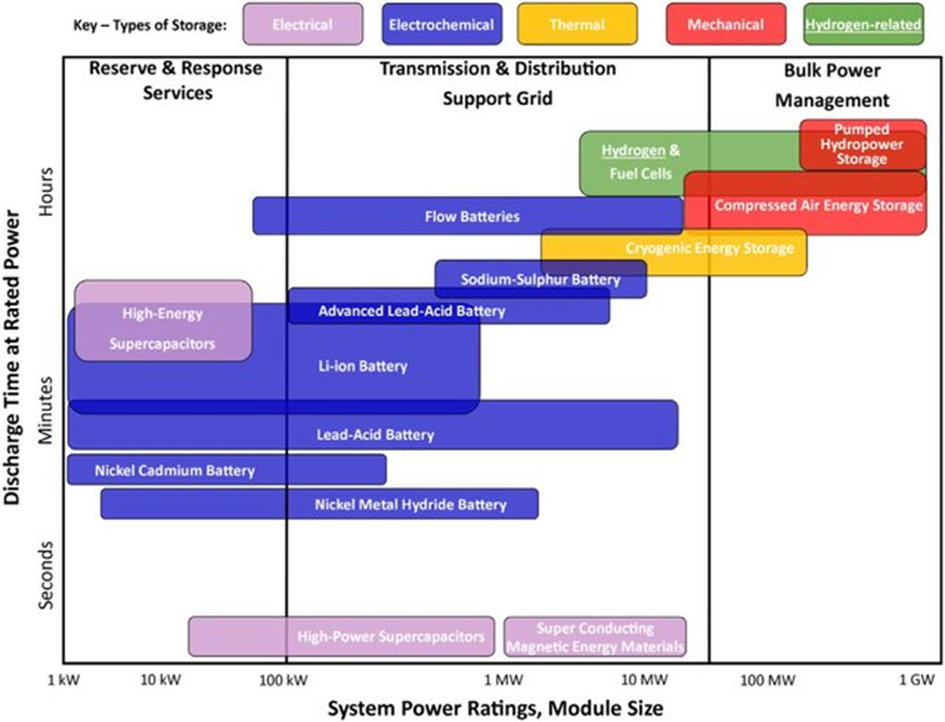
Figure 1. Different type of electricity storage – source : Hydrogen – A sustainable energy carrier, https://www.researchgate.net/publication/312870399_Hydrogen_-_A_sustainable_energy_carrier/figures?lo=1
Multiple means of storage are available (Figure 1). Whether mechanical (potential or kinetic storage), chemical (hydrogen, fuel cells), electrochemical (batteries) or thermal (cold or heat storage), each industrial storage method has its advantages and disadvantages (Figure 1). The choice of technology must be adapted to each particular use and take into account the degree of maturity of the technology and the real costs associated with it.
Storing electrical energy by raising the potential energy of a volume of water is currently the most mature solution to meet the massive needs of the electrical system. This is why dams and pumped-storage stations currently account for almost all the stationary storage capacity installed worldwide.
3. Pumped storage power stations
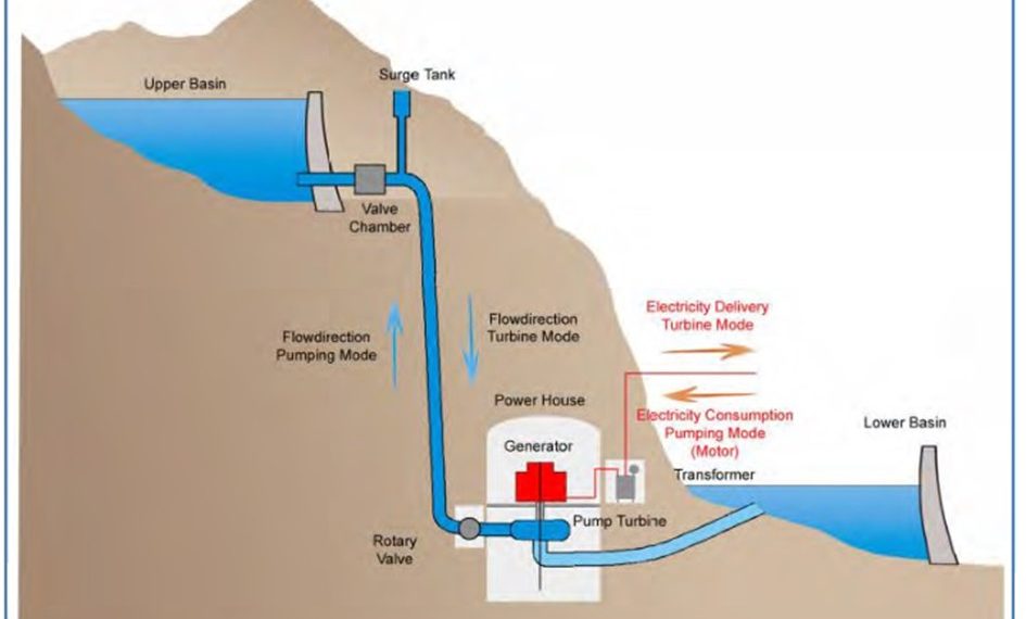
Pumped storage power stations are a special type of hydroelectric facility. These plants have two reservoirs located at different altitudes. Their equipment allows energy to be stored in potential form by pumping water from the lower reservoir to the upper reservoir when demand is low or the cost of energy is low. Conversely, when demand is high or the price per kWh is high, they return electricity to the grid by turbining water from the upper reservoir (Figure 2).
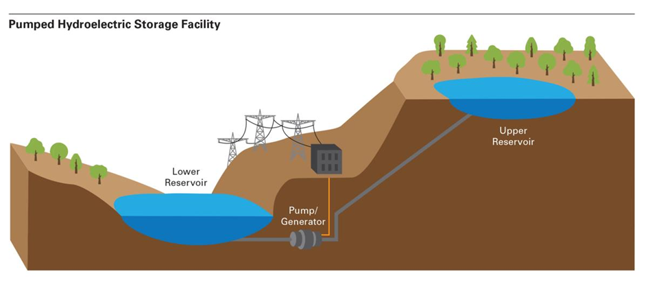
Figure 2. Principe of pumped hydro storage – Source : Dominion Energy wants to build pumped hydro storage facility in coalfields | Latest Headlines | heraldcourier.com
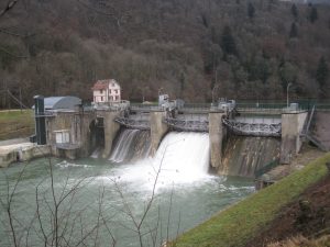
The first facilities using pumped storage appeared at the end of the 1890s in Italy and Switzerland. In France, the first power station operating on this principle was the Lac Noir power station located in the Vosges on the edge of the Alsace plain. It used the night energy of the first power station of Kembs established on the Rhine.
Energy storage by pumping was widely developed in the 1970s and 1990s to optimize the operation of large thermal and nuclear power plants. Powerful stations, up to 3000 MWe of installed capacity, were built for this purpose in Europe, the United States, Japan and a little later in China (Figure 3).
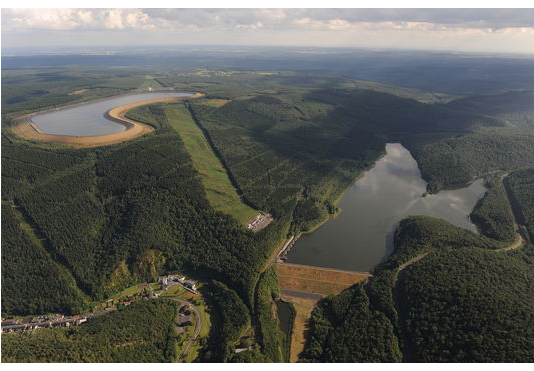
Figure 3. Revin station in France [Source : EDF]
4. Evaluation of a pumped hydro station
Several parameters allow the services provided by a PHS to be characterized:
- the maximum energy stored in the form of potential gravity energy which is proportional to the volume of water stored and the head and which varies from a few GWh to several hundred GWh;
- the installed power in turbining and pumping mode, with a trend towards high-power units exceeding 1000 MWe;
- the time constant, which is the ratio of the maximum storable energy to the maximum power in turbining mode; depending on the volume of their reservoirs, we will speak of a daily STEP if these volumes allow an operation of only a few hours, of a weekly STEP when they allow an operation of several tens of hours continuously;
- the efficiency over a complete cycle, which is the ratio between the energy produced in turbining and the energy consumed in pumping;
- the degree of flexibility, which is linked to the characteristics of the pumps and turbines, i.e. the capacity of each installation to provide services to the power system to ensure network security: frequency and voltage regulation, power adaptation.
Pure PHS operate in a closed circuit with negligible water input. Mixed PHS receive water flows from an intermediate upstream or downstream catchment. Lake and marine PHS use a large lake and the sea as a lower reservoir.
5. Economic Considerations
The efficiency of the pumped storage cycle is between 75 and 85% depending on the type of equipment, which means that in order to benefit from a reserve of energy of 1 MWh, 1.25 MWh must first be consumed.
The use of pumping is therefore directly dependent on the price of electrical energy at a given time. The objective is to fill the upper reservoir by pumping while benefiting from low-cost energy and only turbining this resource in periods of high price. The operation will be profitable when the price difference between purchase and sale covers all the operating costs.
Electricity cannot be stored directly, as needs vary according to the time of day. The massive introduction of intermittent energies whose production, linked to climatic conditions, is a priori independent of demand, is a source of difficulties in maintaining the supply-demand balance. This results in volatile electricity prices that affect production or demand.
This situation becomes a caricature during exceptional events. For example, during the cold snap that hit France in the first half of February 2012, the power demand reached a peak of 102 GWe, requiring all the generation facilities to be commissioned and massive recourse to imports. This resulted in prices of €193,8 per MWh on the EPEX spot market in France, i.e. forty times the average price (Figure 4). Conversely, negative price episodes of -139 € MWh were observed on the German market in December 2011 due to overproduction of wind energy.
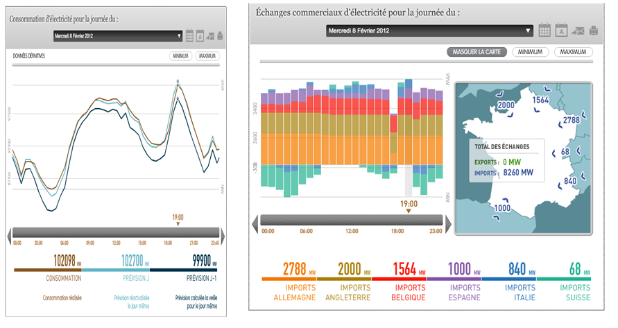
Figure 4. France peak power in February 2012 [Source : RTE eco2mix]
The operating costs include the cost of pumping energy, operation and maintenance costs and taxes.
6. The operation of pump-turbine units
Pump-turbine units are divided into two types of architecture:
- ternary sets which group together on the same shaft: a turbine, an alternator-motor, a pump, all the machines always rotating in the same direction;
- binary sets, which combine on the same shaft an alternator-engine coupled to a reversible turbine-pump, the direction of rotation in pump mode and in turbine mode being reversed.
6.1. Ternary units
The first generation of PHS were equipped with ternary groups with horizontal axis, then the increase in power, and therefore in the weight of the machines, made it necessary to switch to a vertical axis arrangement. In this configuration, the turbine is a Pelton, which must be set above the maximum downstream level, unless a device is used to maintain the free flow under the impeller by back pressure. As for the pump, the non cavitation conditions require it to be sunk below the minimum downstream level, which leads to a high shaft line necessary for the stacking of the three machines, the pivot, the bearings and the coupling device.
The advantage of this architecture is that both machines, pump and turbine, can be designed for their own optimum operating range. As the alternator-motor rotates in the same direction for both operating modes, the turbine allows starting in pump mode directly without requiring a specific auxiliary machine or special procedures to reduce the starting torque.
Without constraints related to starting, it is possible to design the pump with a number of stages and hydraulic characteristics best suited to its field for safe operation.
6.2. Reversible binary units
In this type of design, the pump and the turbine form a single reversible machine by reversing the direction of rotation. Since there are only two machines on the same shaft, the unit is much more compact and allows a significant reduction in the cost of the civil engineering of the power plant and the unit itself.
The turbine pump is equipped with Francis type impellers whose design is the result of an acceptable compromise between optimum pump and turbine efficiency (Figure 5).
The majority of the installations currently in service are non-adjustable units with synchronous motor-generator.
Single or multi-stage for high heads, pump starting requires significant power to overcome the starting torque, so an electric machine capable of providing this power must be added. A solution can be provided by the installation of one or more Pelton type launching units installed in the immediate vicinity, electrically coupled back to back with the pump turbine units during start-up, which is carried out rapidly without damage to the equipment.
The current evolution of technology allows manufacturers to offer adjustable two-stage pump-turbine groups equipped with a distributor with adjustable guide vanes. They can cover heads of 700 to 1200 m.
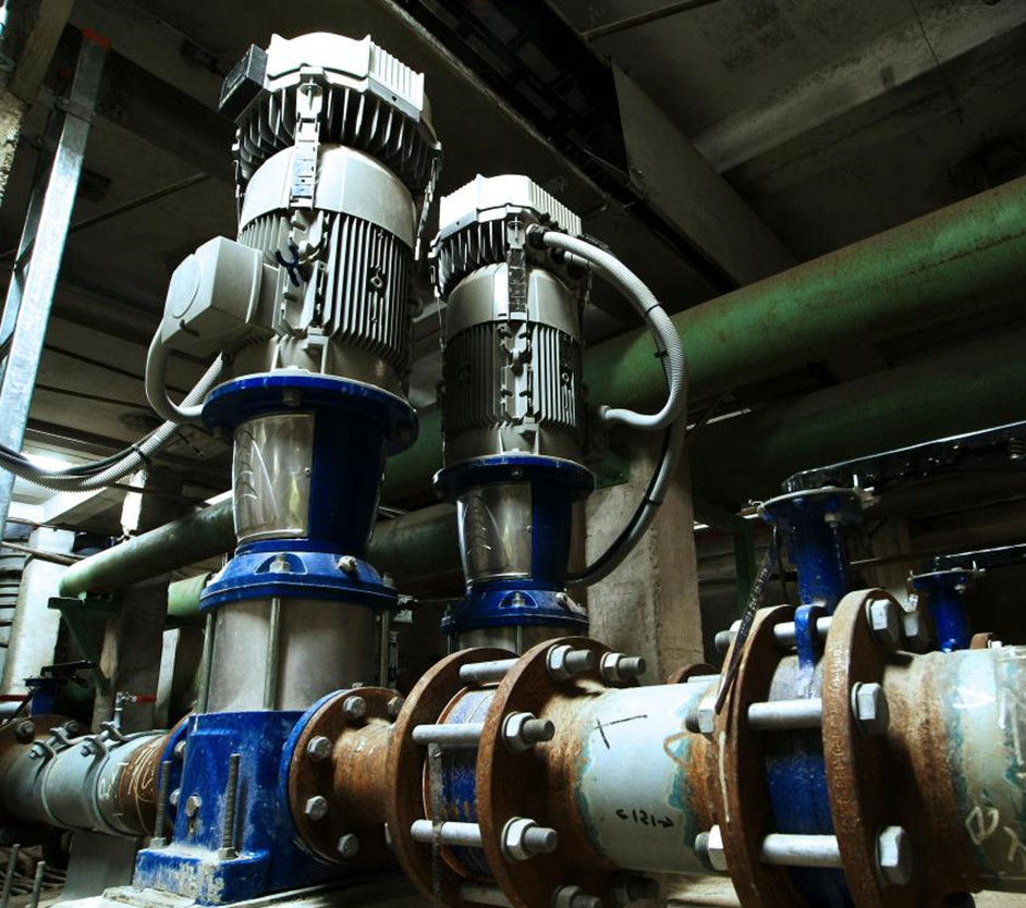
Figure 5. Pump-turbine [Source : Wisegeek, https://www.wise-geek.com/what-is-a-turbine-pump.htm]
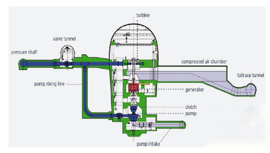
Figure 6. Kops (Austria) PHS station [Source : https://www.andritz.com/hydro-en/hydronews/hn-europe/pumped-storage-by-andritz]
The synchronous alternator motors used in most of the existing power plants of these two types of architecture are fixed speed, the pump is set for an operating point determined by a head, a flow rate and a specific rotation speed and can only be operated over a very limited power range around this point. Due to the variations during operation, the result is an operation with a lower efficiency than the optimum. The ternary group has the possibility to adjust the power of the Pelton turbine by acting on the injectors.
The direct asynchronous start-up from a standstill using the alternator-motor as a start-up engine, which was used for units commissioned in the 1970s, has been abandoned, as in the case of the La Coche PHS in France, due to the constraints on the equipment and the negative consequences on the network. Only small units can still be concerned because of its simplicity.
7. Barriers to overcome and technical progress
Among the various techniques for storing electrical energy, storage by pumping/turbining between two reservoirs at different altitudes is the solution that is by far the most developed in the world, but its development faces several obstacles:
– PHS are large-scale developments because the low energy density of the system (one cubic meter of water falling from 100 meters produces 0.272 KWh) requires, for mass storage, up to several hundred GWh, volumes of water and/or heads that limit their development to mountainous countries;
– the impact on the local environment can be significant due to the surface area required to create the reservoirs; any new project is confronted with its social and environmental acceptability, which conditions its implementation;
– the construction of PHS mobilizes significant investments, a large part of which is devoted to civil engineering, which leads to the search for more economic solutions by over-equipping existing installations or by renewing equipment with new generation pump-turbine groups;
– the regulatory context of access to the network has a direct impact on the profitability of pumped storage. In Europe, countries such as Germany, Italy, Portugal, Switzerland or Austria benefit from a total or partial exemption from network access fees, which is not currently the case in France where the PHS are subject to the network access tariff for all their consumption.
In the face of these obstacles, the IEA’s 2050 Electricity Report recommends the further development of the following two technologies: variable speed and marine PHS.
7.1. Variable speed
The majority of PHS currently in operation is equipped with fixed speed units driven by synchronous motor-generators. They are therefore optimised for a well-defined operating point outside of which the efficiency is lower than its optimum value.
With variable speed it is possible to adapt to variations in flow and head while maximizing efficiency. In addition, this technique offers another important advantage for managing the filling of tanks, namely the possibility of adjusting the active power in pump mode by acting on the rotation speed. Storage is then possible even if the amount of energy available is less than that required for fixed speed operation. By allowing better adaptation to variations in flow and head, variable speed minimizes cavitation and operating instabilities during transients. This technology is therefore becoming the rule for all new equipment and renewals.
7.2. Marine PHS
In order to minimize transmission losses and grid disturbances during strong fluctuations of off-shore wind production, it seems desirable to install the PHS as close as possible to the wind farms along the coastline.
The architecture of this type of power plant is identical to that of an onshore PHS, with the sea as the lower reservoir and an upper reservoir located on land. The power plant can be installed at the foot of a cliff or underground. To date, only one marine PHS exists in the world, the Okinawa PHS in Japan. This is an experimental project built in 1999. The high, artificial reservoir is created on land about 600 m from the shore. The power plant is underground and its equipment consists of a 30 MWe reversible Francis pump-turbine unit operating under an average head of 138 m.
This type of installation has its own constraints: corrosion of metals in contact with seawater, environmental protection against contamination of soil and groundwater by salt, stabilisation of the downstream level against heavy swells to ensure the safety of the units when operating in pump mode.
Futuristic projects built directly at sea are currently proposed, such as the Kerma project in the North Sea (Figure 7). It consists in creating by means of dikes a huge atoll of 10 x 6km with an inner lake level of about 40m below sea level, pumping being used to empty the inner lake using excess wind energy. The installed power could be very important of the order of 1500 MW.
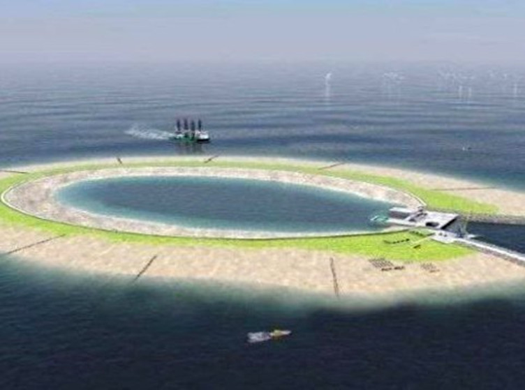
Figure 7. Kerma project in the North sea [Source : https://www.ecohome.net/guides/1500/storing-power-from-wind-farms/]
Such projects will require very heavy investments, which postpones their possible realization to the decades to come.Technological progress in the fields of power electronics and rotating machines, the development of smartgrids, the arrival at maturity of new means of mass storage, the degree of development of intermittent energies, climatic evolution, are all elements which in the decades to come will weigh on the technical and economic choices in the energy field.
8. PHS plants in the world
The need for greater flexibility in the operation of electricity networks through the introduction of storage is historically linked to the operating rigidity of large thermal power plants for which the load variations necessary to adapt to consumption are costly and penalizing over their lifetime. In 2015, it is the strong development of intermittent renewable energies that is driving this need for flexibility (Table 1).
At the global level, 99% of stationary electrical energy storage is provided by PHS. Global capacity reached 140 GWe at the end of 2011 for 400 PHS in operation, including 46 MWe in Europe, 45 in Asia and 21 in the United States (Table 1).
Table 1: Main countries equipped with PHS
|
COUNTRY
|
No. of WWTPs of P>1000MW Corresponding capacity
|
No. of WWTPs under construction of P>1000MW Corresponding capacity
|
Notable installations
|
|
CHINA
|
13 – 17900 MW
|
6 – 8200 MW
|
Huizhou 2450 MW Guangzhou 2400 MW Tianhuangping 1800 MW
|
|
UNITED STATES
|
10 – 14300 MW
|
*
|
Bath Country 3000 MW Ludington 1870 MW
|
|
JAPAN
|
7 – 9300 MW
|
2 – 4400 MW
|
Kannagawa 2820 MW Okutataragi 1930 MW
|
|
EUROPE
|
Installed capacity
|
Capacity under construction
|
Notable facilities
|
|
Germany
|
2580 MW
|
1300MW
|
Goldisthal 1060 MW Markensbach 1050 MW
|
|
Austria
|
1480 MW
|
570MW
|
Malta-Reisseck 1030 MW
|
|
Spain
|
1600 MW
|
850 MW
|
Cortes-LaMuela 910 MW
|
|
Portugal
|
2260 MW
|
950 MW
|
Alqueva 520 MW
|
|
Italy
|
4330
|
*
|
Roncovalgrande 1060 MW Entracque 1320 MW Edolo 1000 MW
|
|
Switzerland
|
3190
|
1900 MW
|
Lintz-Limmern 1000 MW Nant de Drance 930 MW
|
|
France
|
4200 MW
|
*
|
Grand Maison 1790 MW Montezic 910 MW Super Bissorte 730 MW
|
|
United Kingdom
|
2490 MW
|
*
|
Dinorewig 1730 MW
|
China is the most advanced country in this field: in 2009, it had 22 PHS with an installed capacity of 11 GWe, which should be increased to 50/60 GWe by 2020. In Europe, all the countries that are massively developing their intermittent energy production have significant storage needs.
The IEA’s prospective studies foresee a strong development of the existing hydraulic potential, especially in Africa, Asia and Latin America, which would lead to a doubling of the installed capacity by 2050, i.e. more than 2,000 GWe for a global production that could reach 7,000 TWh (Table 2).
|
China
|
United States
|
Europe
|
Japan
|
Rest of World
|
Total
|
||
|
RE % of total energy
|
21%
|
24%
|
43%
|
18%
|
|||
|
2C° Scenario
|
Hydro % total energy
|
14%
|
6%
|
13%
|
12%
|
||
|
WWTP/total capacity
|
4%
|
4%
|
6%
|
11%
|
2%
|
||
|
STEP GW
|
119
|
58
|
91
|
35
|
109
|
412
|
|
|
2C° scenario with mix
|
RE % total energy
|
34%
|
37%
|
48%
|
33%
|
||
|
– Nuclear
|
Hydro % total energy
|
15%
|
6%
|
11%
|
13%
|
||
|
+ RE
|
WWTP/total capacity
|
5%
|
8%
|
10%
|
12%
|
3%
|
|
|
STEP GW
|
179
|
139
|
188
|
39
|
164
|
700
|
For the short term, many projects are under construction, mainly in China and in Europe in countries developing their wind energy production such as Germany, Spain and Portugal.
In the long term, the evolution appears more uncertain and complex. The IEA’s approach is as follows. Assuming that the PHS remains the most suitable tool for electricity storage, the ratio “current pumping capacity/total electricity capacity” characterizes each network. It is low for predominantly hydroelectric networks and high for less flexible networks, i.e. in 2015: 2% in North America, 3% in China, 5% in Europe and 11% in Japan.
With conservative assumptions on the evolution of future energy needs in a given climate context (the 2DS scenario limits the increase in the earth’s temperature to 2°C in the long term), the growth in the value of this ratio, which reflects the additional need for storage, should only concern the networks with the lowest ratios and be moderate. As a result, the global capacity of PHS should be around 400 GWe by 2050. However, this capacity could be increased to 700 GWe in a scenario taking into account the same 2°C limit but an energy mix including less nuclear energy and a greater development of intermittent renewable energies.
9. PHS in France
Six facilities make up the French PHS park, representing an installed capacity of 4.9 GWe for pumping and 4.2 GW for turbining: Grand Maison, Montezic, Super Bissorte, Revin, le Chelas, la Coche (Table 3).
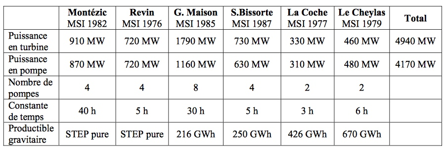
Table 3. [Source : Ursat , Xavier, Henri Jacquet Francillon, et Isabelle Rafaï. «Experience of EDF in the field of pumped storage power plants.» SHF : «Pumped storage Powerplants»]
The high falls of Grand Maison, Super Bissorte and La Coche are equipped with reversible multistage, non-adjustable turbine-pump units with four impellers for Grand Maison and five for La Coche and Super Bissorte (Figure 8).

Figure 8. Grand Maison dam and pump-turbines [Source : EDF]
Montesic, Revin and Le Cheylas are equipped with single-stage, non-adjustable reversible Francis pump-turbine units.The Grand Maison and Super Bissorte power plants have the particularity of associating a unit equipped with Pelton turbines (4 x 150 MWe for Grand Maison, 1 x 150 MWe for Super Bissorte) with a unit equipped with pump turbines (8 x150 MWe for Grand Maison, 4 x 150 MWe for Super Bissorte). For these two installations, the start-up in pump mode is carried out back to back, a Pelton being able to start two groups simultaneously.
There are no plans to start a new major project. Activity focused on the study and implementation of additional equipment and renewals: complete renewal of the four turbine-pump units at the Revin power plant, a new variable speed unit for the Cheylas power plant, and the addition of a high head Pelton unit at the La Coche power plant.
The Encyclopedia of Energy is published by the Association des Encyclopédies de l’Environnement et de l’Énergie(www.a3e.fr), contractually linked to Grenoble Alpes University and Grenoble INP, and sponsored by the Academy of Sciences.
To cite this article, please mention the author’s name, the title of the article and its URL on the Encyclopedia of Energy website.
The articles in the Encyclopedia of Energy are licensed under the terms of the Creative Commons Attribution-Noncommercial-No
Derivative Works 4.0 International License.