What techniques can be used? With what advantages and drawbacks? According to what spatial distribution in Europe?
All generation technologies contribute to the balancing of the electricity network, but hydropower stands out because of its energy storage capacities, estimated at between 94 and 99% of all those available on a global scale (Read: Hydropower storage and electricity generation). This pre-eminence is explained by the numerous advantages of the various forms of storage, which are not offset by certain constraints, particularly those related to environmental and societal impacts.
1. The advantages of hydraulic storage
These range from the maturity of the technology to the massive nature of the storage, not forgetting the speed of response times, the power reserve and the ability to rescue an electrical network under threat.
1.1. Mature technology
Hydraulic storage has been used in Switzerland since the creation of the first local electricity networks at the end of the 19th century, to compensate for the time lag between hydraulic production, which is relatively constant throughout the day, and consumption, linked to the operation of industries. In France, the first Pumped Hydropower Storage (PHS) was commissioned in 1926 at Lake Girotte [1].
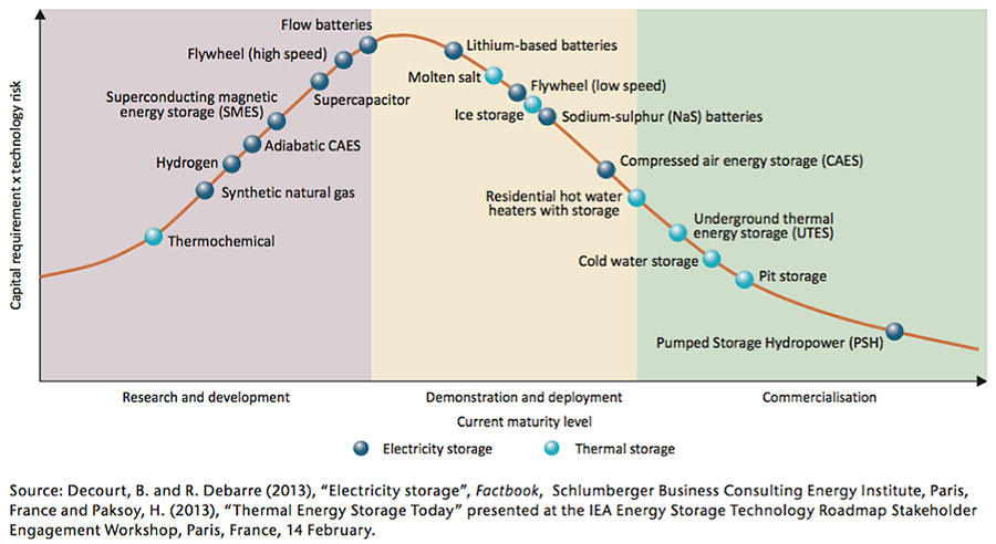
Figure 1: Maturity level of storage technologies – Source : IEA Technology Roadmap Energy Storage 2014
Subsequently, pumped storage plants were built for different reasons in different countries: in France, to accompany the development of nuclear power plants, which were not very flexible at the time; in Norway, to provide seasonal storage, in the form of filling up in summer thanks to the high flows from melting snow, followed by production in winter, and more generally for daily storage by filling up at night and producing at peak times of the day (Read: Pumped Hydropower Storage). In 2019, the development of pumped storage is directly linked to the context of market deregulation and the development of intermittent energies, which requires storage means among which it is the most mature (Figure 1). (Read: Stockage hydraulique : atouts et contraintes).
1.2. massive storage
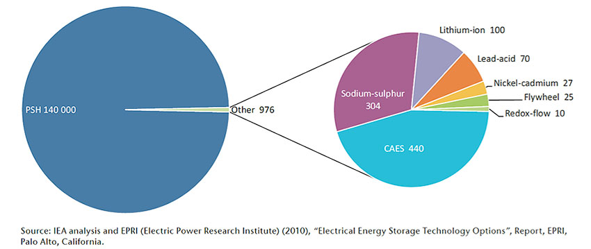
Among the storage technologies currently available, with capacities of up to several GWh, hydro is the only technologically and economically mature medium capable of massive storage. This can be seen by comparing PHS technology with other storage technologies in terms of capacity and discharge time (Figure 2), hence its supremacy over other storage technologies (Figure 3).
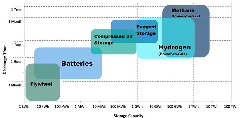
Figure 2: Storage technologies : discharge time in function of storage capacity [Source : European Commission, Commission staff working document, Energy storage – the role of electricity]
For a highly integrated grid such as Europe’s, pumped storage using hydroelectric power plants equipped with large water reservoirs represents a storage capacity and flexible production of several MW to several thousand MW. These installations, spread throughout Europe, are distinguished by a wide variety of water situations and reliefs, with exploitable falls ranging from a few metres to several hundred metres in height (Read: Stockage hydraulique : capacités de pompage-turbinage).
1.3. Mass storage: the example of Norway
The three main regions of hydraulic storage in Europe are Norway and the Scandinavian region, the Alpine region and, to a lesser extent, the Pyrenees.
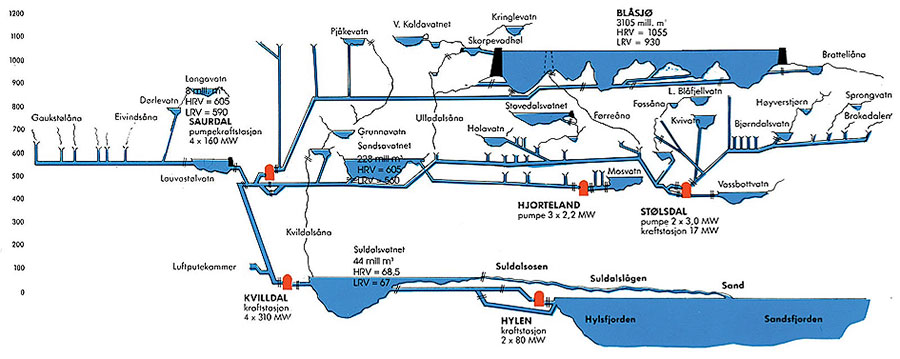
Norway, with a 96% hydroelectric power mix, produces on average 123 TWh of electricity per year and has a storage capacity of 85 TWh. Pumping is not used there on a daily or weekly cycle but in the form of seasonal pumping between very large reservoirs. In addition, the pumped storage capacity is currently limited by the electrical capacity of the installed pumps and turbines and the size of the upstream reservoir. Since the reservoirs in Norway are very large, they are connected to other conventional hydroelectric generators. For example, the Blåsjø lake (Blue lake), which alone has a reservoir capacity of 7,8 TWh, is used as a reservoir for several hydroelectric power plants (Figure 4).
For these reasons, Norway could play the role of Europe’s battery. The incorporation of pumped storage plants could also improve the quality of the power supplied, which has tended to deteriorate in recent years. It could provide an important back-up to the electricity system of the European continent. Preliminary studies on the possibilities of expanding Norway’s pumped storage capacity show that there is a potential of 10-20 GW of pumped storage capacity if the existing reservoirs are used in a different way. To achieve this result, several challenges will have to be faced:
- increased transmission capacity between Norway and the European continent;
- increased social acceptance for new transmission lines;
- adoption of business models for the management of pumped storage plants.
1.4. Response time and flexibility
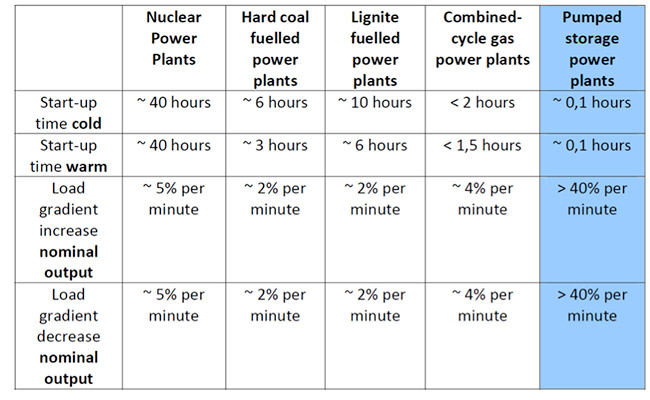
Flexible, hydraulic storage fulfils a variety of roles in reinforcing RES for services with different timeframes of operability: instantaneous, daily or seasonally. These storage options are not only essential for developing multiple renewable energy sources, but also for ensuring continuity of supply and increasing energy autonomy. This is evidenced by the rapid start-up and load take-off of hydroelectric plants in general and pumped storage plants in particular, compared to thermal, conventional or nuclear power plants (Table 1).
Table 1: Flexibility of different power generation technologies. Source: Eurelectric 2011
Whereas the installations of the 1970s and 80s were mainly equipped with reversible pump-turbine units at fixed speed (synchronous machines), today’s installations are often equipped with variable speed units or ternary units, which improve performance in terms of flexibility.
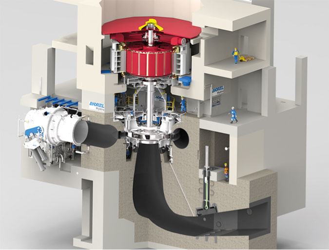
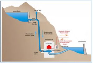
Reversible units consist of a pump that can operate as a turbine and a reversible alternator-motor (Figure 5). For falls over 600 m, it is necessary to multiply the number of stages, as at Super-Bissorte (1187 m, five stages) or Grand-Maison (949 m, four stages).
These units are not adjustable in pump mode. To be able to adjust the power in turbine mode, it is necessary to have a distributor, which is only possible for single-stage units and, more exceptionally, for two-stage units, as at Yang-Yang, in South Korea (832 m).
The technology of variable speed units first appeared in Japan in the early 1990s with the Yasigawa power plant, and has become widespread since the early 2000s [2]. For example, two of the four units at the Goldhistal power plant in Germany are units whose speed can vary between 300 and 346 rpm, which makes it possible to adjust the pumping power between 170 and 300 MW. This speed variation allows for frequency control in pumping. The speed variation also makes it possible to optimize the turbine efficiency value at partial loads and under variable heads.
In terms of speed of response, modern variable speed drives can start up in two minutes and change modes in five minutes.
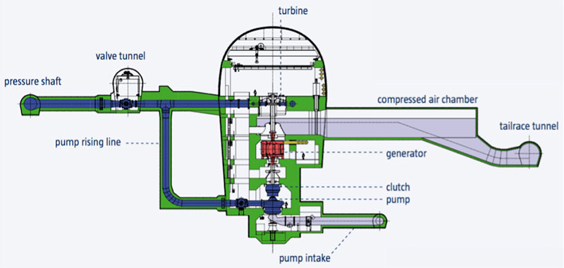
The other technology available on the market is ternary units, which consist of a pump, a hydraulic coupler, a turbine and an alternator-motor (Figure 6). They are generally more expensive than reversible units, but they have the advantage of designing the two hydraulic machines, pump and turbine, in an optimal way, each one being perfectly adapted to its field of operation, unlike reversible machines whose hydraulic design is always the result of a compromise. This architecture also makes it possible to adjust the turbine power regardless of the head range.
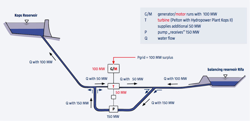
The power, and therefore the frequency, can be adjusted during the pumping phase by means of a hydraulic short-circuit (Figure 7). In this mode of operation, the power absorbed from the network, e.g. the difference between the nominal power of the pump and the power supplied by the turbine, can be adjusted very precisely between 0 and 100 %. This type of operation naturally leads to a slight loss of efficiency.
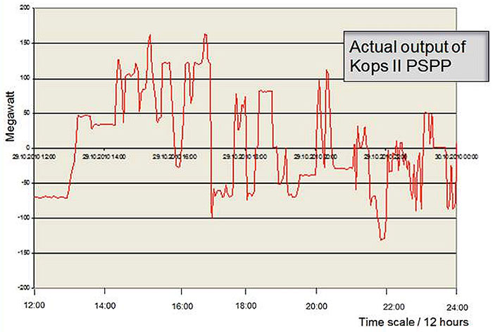
The fact that it is not necessary to change the direction of rotation to change the operating mode means that the time taken to switch from one mode to another can be reduced to less than a minute. This rapid response of variable speed reversible units and ternary units makes them incomparable in terms of frequency regulation capacity (both pumping and turbining), spinning reserve, voltage regulation (reactive power) and capacity to integrate intermittent energy sources. The power output of a ternary unit of the Kops II power plant with several changes of operating mode over a 12-hour period (Figure 8) illustrates these characteristics.
1.5. System power reserve
Power reserve, or operating reserve, is the generating capacity available within a limited time interval to meet demand in the event of a generating unit outage, a disruption in power supply, or a peak in demand. Most power systems are designed so that under normal operating conditions, the power reserve is always at least equal to the capacity of the largest generator plus a fraction of the peak load. Spinning reserve is the energy stored by rotating the turbines of large-scale power plants, which stabilizes frequency and power on the high-voltage grid (Figure 9).

Figure 9: Storage systems power reserves [Source: Assessing Storage Value in Electricity Markets -CE FP7]
The power reserve consists of a synchronized (spinning) reserve as well as a stopped (non-rotating) or additional reserve:
- synchronized reserve, which is the additional capacity available to increase the power supplied by generators already connected to the grid; for most generators, this increase in power supply is achieved by increasing the torque applied to the turbine rotor;
- the stopped or additional reserve, which is the additional capacity not connected to the grid but capable of being connected within a given time.
In an isolated system, available power is obtained from fast-start generators. In interconnected networks, the available power can be included within a given time frame by importing power from external networks or stopping the export to external networks. On islands not equipped with spinning reserve, storage can be substituted by batteries using lead, nickel, lithium or sodium. Where storage technologies connect to the high voltage grid, this operation is the responsibility of the transmission system operator.
1.6. Other characteristics and summary
In addition to its massive nature, flexibility, fast response times and power reserve, hydraulic storage has a few other advantages:
- overall efficiency: the efficiency of a pumped-storage cycle is in the range of 75-85% ;
- memory effect: unlike electric batteries, in particular Ni-Cd technology, pumped storage stations obviously do not have any memory effect, their capacity remains intact whatever the number and intensity of the cycles performed ;
- lifespan and number of cycles: the life span of hydroelectric installations in general, and therefore of pumped storage installations in particular, is long: the first structures, now more than a century old, are generally still in a satisfactory condition.
It should be added that the reservoirs of the PHS, in particular pure PHS, therefore without external inputs, are not subject to filling phenomena by sediments.
The main equipment (production units, winches) have a service life of several decades, and partial renovations or replacement can even extend the service life almost without limit. Assuming a service life of 30 years, the possible number of cycles can be estimated to be at least 50,000 before the equipment is replaced.
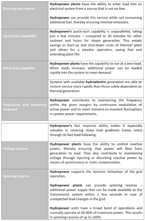
In total, the pumped storage facilities can be characterized (Table 2) as well as the stabilization, regulation, reserve and start-up reactivity services, also called auxiliary services or system services (Table 3).
Table 2 Main characteristics of PSP (VS = variable speed, TS = ternary groups) – Source: European Association for Storage of Energy (EASE) 2017
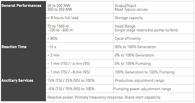
Table 3 Auxiliary services that storage hydro plants can provide – Source: Eurelectric 2011
1.7 Grid backup: example of the 4 November 2006 blackout
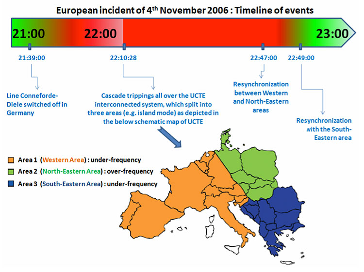
In addition to its many advantages, hydraulic storage can also rescue a faulty grid, as was the case in Europe during the incident of November 4, 2006, which caused power supply interruptions to more than 15 million homes. Immediate action by all Transmission System Operators (TSO).
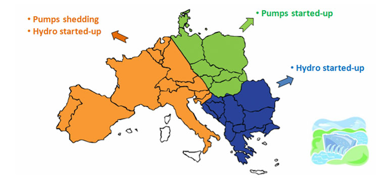
TSOs prevented this disruption from becoming a Europe-wide blackout. How did it happen? The chain of events led to the occurrence of this disturbance (Figure 10) in three zones Western Europe (zone 1), Eastern-Northern Europe (zone 2) and Southern Europe (zone 3).
The splitting into three systems led to a strong imbalance between these zones. Due to the large frequency fluctuation excursions, a significant number of generating units, more than 10,000 MW in the Western region, connected to distribution networks, were disconnected from the grid due to their protection systems. Investigations identified non-compliance with the N-1 criterion and insufficient coordination between TSOs as the two main reasons for this disturbance.
In order to quickly restore the balance between electricity production and consumption, several procedures were launched, among which run-of-river hydropower, with hydro reservoirs and pumped storage plants, played a major role (Figure 11). In France, not only reservoir hydroelectric plants have allowed to inject important powers (2000 MW in 11 minutes, more than 5000 MW in 40 minutes) but run-of-river plants have also contributed. For example, the facilities of the Compagnie Nationale du Rhône (CNR) made it possible to release 270 MW in two minutes, the initial power being restored nine minutes after the incident.
2. Constraints and socio-environmental impacts
Despite its many advantages, hydraulic storage can be penalised by constraints related to its environmental and societal impacts.
2.1. Constraints
Many potential sites are limited by geographical and geological constraints and/or impacts on the environment and other human activities. Compared to chemical storage, the energy density of these facilities is low and their advantage in terms of capacity is due to the large volumes involved [3].
However, these characteristics require facilities with high initial investment, the profitability of which is directly linked to the regulation of the electricity market and the valuation of system services.
2.2. Social-environmental impacts
The social-environmental impacts depend on the type of development considered, depending on whether they are made up of two reservoirs completely separated from the hydrological network (the case of totally artificial reservoirs in particular) or whether one or both reservoirs are connected to a river.
In the first case, the environmental impacts are less important as they only affect aquatic ecosystems to a very limited extent.
In the second case, the impacts are generally of the same type as those of conventional hydroelectric schemes: they are related to aquatic biodiversity, hydrology and hydrogeology, sediment transit and land use. On the other hand, the operation of a pumped storage facility does not consume any raw materials and does not produce any waste.
Pumped-storage facilities can be created from existing facilities and create an additional reservoir, generally completely artificial, thus with minimal impact on aquatic life. The works are often underground. The main impacts will then be related to the consequences of repeated tidal movements in the reservoirs, with the creation of barren areas on the banks (Read: Hydroelectricity: environmental and societal impacts).
Notes and references
[1]Viollet P.L. (2005). Histoire de l’énergie hydraulique. Presses de l’école nationale des Ponts et Chaussées.
[2]There are two technologies for variable speed generators: either a synchronous machine supplied by a current converter sized for the rated power of the machine, which limits its use to low power machines, or an asynchronous machine equipped with a converter on the rotor circuit, thus allowing the power of the converter to be reduced to about 15% of the rated power of the machine.
[3] As an example, the Grand-Maison WWTP is equipped with 8 reversible units with a pumping capacity of 135m3/s for a power of 1270 MW, which gives an energy density of 2.61 Wh/kg compared to the density of the batteries (25 to 25 Wh/kg for lead-acid batteries, 120 to 180 Wh/kg for Li-Ion batteries)
Additional bibliography
[1] Argonne National Laboratory (2013). Modeling Ternary Pumped Storage Units. Available at https://www.osti.gov
[2] Avellan F. (2012). Evolution of pumped storage units. Current situation, technologies and new projects. Bulletin Electro-suisse 2/2012 pp. 37-40.
[3] EASE/EERA (2017). European Energy Storage Technology Development Roadmap 2017 update. Available at http://ease-storage.eu
[4] European Environment Agency (2018). Renewable energy in Europe – 2018 Recent growth and knock-on effects. Available at https://www.eea.europa.eu/
[5] Eurelectric (2015). Hydropower supporting a power system in transition. Available at https://www.eurelectric.org
[6] Eurelectric (2011). Hydro in Europe: Powering Renewables. Full report and annexes. Available at https://www.eurelectric.org
[7] International Energy Agency (2014). Technology Roadmap. Energy Storage. Available at https://www.iea.org
[8] European Commission. Joint Research Center (2012). Pumped-hydro energy storage: potential for transformation from single dams. Available at https://ec.europa.eu/jrc/en
[9] European Commission. Joint Research Center (2013). Assessment of the European potential for pumped hydropower energy storage. Available at https://ec.europa.eu/jrc/en
[10] European Commission. Joint Research Center (2013). Assessing Storage Value in Electricity Markets. Available at https://ec.europa.eu/jrc/en
The Encyclopedia of Energy is published by the Association des Encyclopédies de l’Environnement et de l’Énergie(www.a3e.fr), contractually linked to Grenoble Alpes University and Grenoble INP, and sponsored by the Academy of Sciences.
To cite this article, please mention the author’s name, the title of the article and its URL on the Encyclopedia of Energy website.
The articles in the Encyclopedia of Energy are made available under the terms of the Creative Commons Attribution – Noncommercial – Nonmodification 4.0 International license.


