
The conversion of solar radiation into heat and electricity is at the heart of any transition to sustainable energy systems. But before reviewing the various technologies for achieving this, a detour into the theoretical basis of this energy source is essential.
The conversion of solar radiation into calorific, electrical or chemical energy for our purposes is what is known as solar energy. Over time, this energy has become one of the major sources of renewable energy alongside biomass, hydraulic energy and wind energy.
The use of solar energy is still quite low compared to other energy sources. Even among renewable energies, it is still in the minority, which is a paradox since the energy corresponding to solar radiation received at the earth’s surface is by far the most abundant resource among all those available to us.
In order to understand the different ways of converting the radiation from our star, some theoretical bases are essential. We can acquire them by starting with the resource, i.e. the energy coming from the sun and received at the earth’s surface, and then by explaining the physical principles governing the interaction between the radiation and the matter, which lead to the conversion of this radiation into heat or electricity in different bodies.
1. The Resource: Solar Radiation at the Earth’s Surface
How does the energy released by the sun reach our planet by radiation and how can it be measured?
1.1. How the sun works: conversion of mass into electromagnetic energy by nuclear fusion
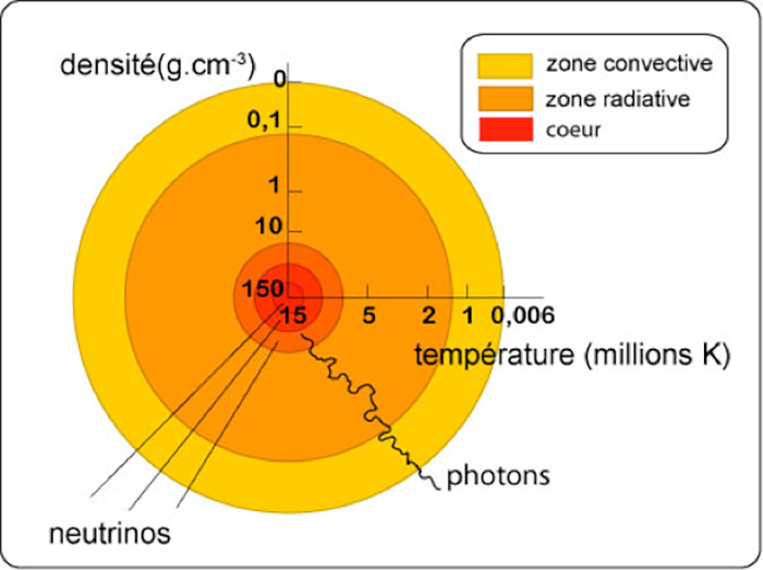
Figure 1. The core of the sun.
The sun, our star, is the seat, like all stars, of thermonuclear reactions releasing an enormous amount of energy [1]. It has been shown that it is the fusion reaction of four hydrogen atoms into one Helium 4 atom that is involved (nuclear fusion reaction):
4 H –> He + Energy
The mass loss involved in this reaction in the sun is 5×10⁹ kg per second, or 5 million tons per second. This implies according to the equivalence equation Mass (m)/Energy (E), the famous equation : E = mc2 where c is the speed of light, a power of 4×1026 W or 400000 billion of TW, an absolutely considerable power.
This energy is released in the heart of the sun, the core (Figure 1). Complex energy exchanges take place between this core and the periphery, first in the form of radiative energy in an intermediate zone called radiative, then through convection in the peripheral layer called convective.
Figure 2. Spectrum of the light.
The extremely high temperature in the core (15 106 K) drops to 5900 K at the outer surface. In fine, all this power is evacuated outside essentially in the form of electromagnetic radiation (light) by this peripheral surface whose temperature is 5900 K and which is called the photosphere. The spectrum of this emitted light is thus very close to that of the black body at this temperature (orange curve in Figure 2).
This spectrum covers a wide range of wavelengths from the deep infrared to the ultraviolet. Of course, the maximum intensity is in the middle of the visible spectrum, which is not surprising. Our eyes have adapted, in the course of evolution, to capture the maximum number of photons.
1.2. Solar radiation at the earth’s surface
Figure 3.The incident power of the sun.
This radiation then reaches the earth’s sub-atmosphere without any problems in proportion to the solid angle related to the distance and to the size of our planet. The power received by this illuminated hemisphere, which is very small compared to the global power of the sun, still represents a gigantic power of 170 000 TW. This flux is more than 2000 times greater than our current energy needs.
If we compare this annual flow to the fossil energy resources stored in our subsoil (Figure 3), we can see that direct conversion, even if diffuse, represents a considerable resource.
Figure 4. Earth absorption and reflexion.
This radiation will undergo a number of interactions with the atmosphere and the surface of our planet (Figure 4) [2]:
- reflection of part of the radiation by the earth’s surface or by particles in the atmosphere (clouds and dust);
- absorption of some photons by gases in the atmosphere (water vapour, CO2, ozone O3 and O2) for certain specific wavelengths (Figure 5) or by dust;
- absorption by the soil or water present on the surface of the globe.
Figure 5. Solar irradiance spectrum.
The warming induced by the absorption of radiation on the ground or in the atmosphere will induce a number of phenomena:
- evaporation of water and its re-condensation into the atmosphere to create clouds and rain;
- air movements (winds) related to temperature differences from one place to another in the atmosphere (creation of highs and lows);
- re-emission of part of this absorbed energy into space in the form of long-wave infrared radiation (red arrows in Figure 4)
The major renewable energies of hydropower and wind power result from these interactions of radiation with the atmosphere. Ultimately, the radiation is partly converted into mechanical energy either by the elevation of water masses or by the movement of air masses. Biomass is a direct conversion of radiation into chemical energy by transforming atmospheric CO2 into organic material.
Figure 6. Earth seasonal cycles.
Radiation at the Earth’s surface is of course variable. The first cause is the earth’s movements in relation to the sun: on the one hand, its rotation on itself around the axis of the poles, which leads to daily cycles, and on the other hand, its revolution around the sun, which, due to the inclination of the axis of rotation, leads to seasonal cycles (Figure 6).
These cycles are dependent on the latitude of the place and imply important changes in the availability and type of variation of solar energy according to the place and the season.
A second cause of variation is the large amount of water in the atmosphere that forms clouds. Clouds act as a strong radiation mask, reducing the density of the radiation but not cancelling it out. This mask also displays a large variability that is only strongly attenuated in continental desert regions. This is the meteorological variability. The attenuation of the radiation is more or less important according to the density of the cloud in terms of particles constituted by the water droplets. The latter reflect and rebroadcast the radiation towards space and also towards the ground.
In the presence of a cloud, the radiation received by the earth’s surface no longer comes essentially from the solar disk but in a notable part, even the majority, from the whole solid angle excluding the solar disk. The average cloud cover also depends strongly on the place and its climate. The variation, contrary to that linked to the movement of the star, is much more random but partially predictable from weather forecasts.
The climate has a strong influence, not only on the intensity of the variations, but also on the annual global irradiance, i.e. the integral of the radiation (irradiance) received at a location per year. The knowledge of this integral is important to assess the profitability of an installation.
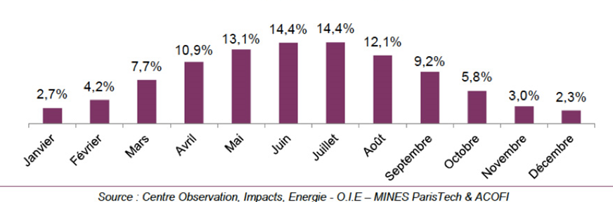
Figure 7. Monthly irradiation in France: annual repartition in percentage.
The two causes of variation (astral cycles and climate) combine to explain the important causes of annual variation. An example is given below for France (Figure 7). The effect of climate (high cloudiness in the winter months) is added to the reduction in day length to explain the low contribution of the winter months to the global annual irradiance.
1.3 Methodology for measuring solar radiation at the Earth’s surface and insolation data
Due to the interactions of radiation with the atmosphere and to properly appreciate the energy flux received by a solar collector according to its type, it is common practice to measure several types of irradiance parameters [3] (energy flux density per unit area). These types of irradiance are expressed in J/m2 or more often for practical reasons in Wh/m2:
- a first parameter is the direct irradiance received at a given point from the solar disk [4], called Direct Normal Irradiance – DNI ); it is measured by a device constantly pointed at the solar disk and equipped with a diaphragm allowing to eliminate the radiation not coming from the solar disk; this type of device is called a pyrheliometer; this DNI measurement is the one used for concentrating solar systems (see below);
- a second parameter is the Diffuse Horizontal Irradiance which quantifies the irradiance received by a horizontal surface at the Earth’s surface from the whole sky excluding the solar disk, thus from a solid angle of 2pi steradians (180°); as indicated in 4, molecules and particles in the atmosphere re-radiate part of the radiation they receive towards the Earth’s surface; this parameter is called Diffuse Horizontal Irradiance (DHI)
- a third parameter is the Global Horizontal Irradiance (GHI), which quantifies the irradiance received by a horizontal surface at the Earth’s surface from the entire sky, including the solar disk; GHI is equal to DHI + DNI cos(Z), where Z is the zenith angle, the angle between the straight line connecting the point on the surface to the sun and the vertical line of that location; this is the parameter used for flat-plate sensors. Note that it only quantifies the irradiance received by the sensor if it is placed horizontally; if the flat-plate sensor is oriented differently, geometric corrections will have to be applied to GHI and DHI.
Figure 8. Direct normal irradiation in France.
From the recording of these data at various locations on the planet and over a minimum period of one year, it has been possible to measure the integral over time of these irradiances called irradiation at each location and to draw up irradiation maps called respectively, Normal Direct Irradiation, Diffuse Horizontal Irradiation and Global Horizontal Irradiation. These data and maps are valuable documents for predicting the amount of energy available and assessing the interest and profitability of an installation. An example of DNI and GHI maps for France and for the world is given in Figures 8 and 9. A number of these data and maps are available for free or for a fee on specialized websites.
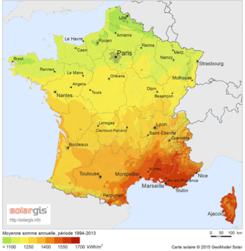
Figure 9. Global horizontal irradiation in France.
From these maps we can see:
- significant differences in the available energy according to the places but with a relative amplitude of GHI which remains finally more moderate than what one imagines spontaneously (as an example there is only a factor of the order of two between the sunniest and the least sunny places in Europe);
- unsurprisingly, a maximum of irradiation in tropical areas and in particular in the continental deserts of these areas;
- an advantage for high altitudes (at equal latitude).
2. The physical principles of converting solar radiation into heat or electricity
The conversion of solar radiation into useful sources of energy requires solar collectors whose operation can only be understood by tracing the interactions of solar radiation (photons) with matter.
2.1. The interaction of radiation with matter
In the range of wavelengths considered, the photons of solar radiation are likely to transmit their energy to the peripheral electrons of the atoms of the matter in which they penetrate. This is the so-called photoelectric effect.
Figure 10. Photoelectric effect. [Source : author]
According to this phenomenon (Figure 10), if this interaction occurs, the photon gives up all of its energy quantum to the electron involved. It is the demonstration of this effect that allowed Einstein to show the quantization of electromagnetic energy. The latter cannot thus be regarded only as a vibratory phenomenon: one has in fact a duality Wave/Particle at the same time for the electrons and for the photons. This revelation has turned physics upside down and is at the origin of the discovery of quantum mechanics.
Understanding these fundamental mechanisms is essential if we want to understand the functioning of Solar Energy and especially Photovoltaic Energy.
In solids, because of the proximity of atoms and because of their wave character, the peripheral electrons of atoms occupy discrete and quantified energy levels very close to each other. These energies no longer depend only on the atom from which they originate, but on all the atoms of the solid and their position relative to each other.
This multitude of closely spaced energy levels are thus spreaded in large energy intervals, which are called electronic bands, while in other intervals, there are energy levels which are available but not occupied.
Figure 11. Conductors, semiconductors or insulators [Source : author]
A distinction is made between different types of materials according to the structure of these bands and the population of peripheral electrons available. Those in which, at very low temperatures, the most energetic electrons completely fill a band called the valence band are called semiconductors or insulators, depending on the case (Figure 11).
Above the valence band, there is a band of energy called the forbidden band, which covers a segment of energy that electrons will not be able to take, and even higher in energy, a band of energy that is not occupied at low temperature but is available and can be partially populated by electrons, depending on the case. This band is called the conduction band. The energy width of the band gap is called Eg.
In these materials, we can have electrical conduction with free electrons, which can propagate in the solid, only if they cross the energy barrier constituted by the band gap of width Eg and pass into the conduction band.
It should be noted that the place they free in the valence band will also open the possibility of a movement of electric charge of the same value as that of the electron but of reversed polarity (of positive charge and not negative). It is in fact this localized absence of electron which will be able to propagate. We call this mobile positive charge simply a hole.
An insulator is a semiconductor but with a very high energy gap Eg, so that it is very difficult for an electron to cross this energy barrier. Electronic conduction will therefore be extremely limited.
The second major category of materials is that of conductors (metals). In these, there is no band gap. In fact, valence and conduction bands overlap. Electrons are free and mobile even at low temperatures and in the absence of excitation: very little energy is needed to place them in a state where they are able to move.
If we focus on the impact of this electronic band structure on the interaction Photon/Matter and in fact Photon/Electrons, we observe that when a photon of energy En penetrates one of these solids, it will be able to give up its energy to an electron of energy E1 thanks to the photoelectric effect, provided that there is a level E2 = En+ E1 available in this solid.
According to this phenomenon, we can distinguish three cases.
- The case of the semiconductor where the energy of the photon is lower than Eg. As there is no energy level E2 = En + E1 available for the electron, this photon will not be absorbed by the solid. It will pass through the material and come out without giving up any energy. The material will thus be transparent for all photons of energy between 0 and Eg. If Eg is between 1.5 and 3eV (visible spectrum) the material appears colored because it allows only a part of the spectrum to pass. If Eg is lower than 1,5 eV it appears black to us and if Eg is higher than 3eV (visible spectrum) it appears completely transparent or white to us.
- The case of the semiconductor where the energy of the photon is higher than Eg. The photon will in all probability give up its energy to an electron whose energy will populate a level in the conduction band. This electron will be free to move and under certain conditions an electric photo-current can be created. A free “hole” will also be created which can also participate in photoconduction. We will then talk about Photo-generation or generation of Electron-Hole pairs.
- The case of metal. Here and whatever the energy level, the photon will systematically give up its energy to an electron which will join another energy level but in the same energy band where it was initially. It will not be able to stay in an excited state and will return to populate the initial population of electrons in the lower levels by giving up its excess energy in the form of heat by interaction with phonons (mechanical vibrations of the atomic lattice). This will result in a rise in temperature of the material. In the end, the solar radiation energy will be totally converted into heat.
These characteristics and phenomena will therefore govern the ability of this or that material to be a good thermal collector or a good photovoltaic collector.
For thermal collectors, the objective will be to capture the maximum number of photons in the entire spectrum and to be satisfied with the natural transfer of their energy into heat in the form of network vibration. Therefore, metals will be used with some subtleties in their surface treatment (see 2.2).
It is important to note, however, that the conversion of photon energy into heat is the most common case, including semiconductors and organic materials. Many conditions are required (see 2.3) for some of the energy to be finally converted into electrical energy capable of powering an external circuit (the case of photovoltaics), or into chemical energy (the case of photosynthesis).
Thermodynamics teaches us that systems tend towards a state of maximum disorder and therefore towards maximum entropy, the heat that represents the energy of maximum entropy.
2.2. The physical principles for efficient thermal conversion
The conversion of radiation into thermal energy is natural and common in most materials. It is enough to place these in front of the sun to notice a rise in temperature.
However, obtaining an efficient solar thermal collector with a maximum conversion efficiency (ratio between the thermal energy recovered at the collector outlet and the initial radiation energy) is not self-evident. A number of conditions must be met:
- an efficient capture of the radiation by the absorber material, avoiding in particular a strong surface reflection,
- minimization of heat loss in the collector, either by re-emission of infrared radiation or by loss through conduction,
- a good heat transfer between the absorber material and the heat transfer fluid, the fluid that circulates in the collector and that allows the heat to be extracted and transferred to the points of use.
Figure 12. Solar thermic.
The choice of absorber material is particularly important. Its absorption coefficient must be maximum over the whole spectrum and its reflection coefficient minimum, in order to capture the maximum number of photons. Moreover, any heated material emits photons. Given the temperatures involved, this radiation is emitted in the infrared spectrum. This emission acts as a loss and must therefore be minimized.
The amount of energy emitted by radiation depends not only on the temperature of the body, but also on an intrinsic characteristic of the material, the emissivity. It is therefore in the interest of the user to choose a material with low emissivity in the relevant wavelengths. To do this, a specific layer must be added to the surface of the metal to optically limit the emitted infrared radiation by resonance or interference effects. These materials, which are good absorbers in the visible and near infrared spectrum and weak emitters in the infrared spectrum, are called “Selective” materials [6].
In order to minimize the infrared radiation, the greenhouse effect is also often used (Figure 12). This involves adding a material that is transparent to the sun’s spectrum but absorbs the far infrared spectrum, such as a glass plate, while leaving an air or gas gap.
Figure 13. Yield and operating temperature.
It is then necessary to distinguish two cases, the sensors with or without concentrators. Indeed, if one seeks to obtain high temperatures beyond 200°C for certain applications, in particular for thermodynamic power plants, one will have to use solar concentrators (optical devices aiming at concentrating the sun’s rays). In the latter case, the selective material must be adapted to the target temperature and therefore to the wavelengths of the infrared radiation considered.
In the case of a thermodynamic power plant in which the heat is converted into mechanical work and ultimately into electricity, the variation of the overall energy efficiency with the operating temperature will present a maximum (Figure 13). Indeed, if the Carnot efficiency of the power plant increases linearly with the temperature, the losses by radiation are proportional to the product of the emissivity of the absorber material and the temperature at power four. Radiation losses largely take precedence at high temperatures.
2.3. Photovoltaic conversion
Figure 14a. Energy levels in a n-type semiconductor material.
Photovoltaic conversion requires the use of semiconductor materials [7]. In these materials, provided that the energy of the photons is sufficient, the photoelectric effect will result in the photogeneration or generation of electron-hole pairs which will become mobile and will be able, under certain conditions, to transmit part of the electrical energy thus acquired to an external circuit.
The condition for this generation is that the energy of the photo En is greater than Eg, the width of the band gap of the material. It is important to understand that the creation of free electrons is not sufficient in itself to produce a photo-current and the emergence of an electrical generator. In order for the electrons to be able to circulate in the external circuit and give up the energy thus acquired, it is also necessary to create an asymmetry of potential energy so that the free electrons (and holes) go mainly in one direction rather than another and do not move in a totally random way. The idea here is to create a driving force for these charges.
Figure 14b. Energy levels in a p-type semiconductor material.
To do this, we exploit the possibility of joining two semiconductor materials for which the profile of energies available to the electrons is not identical on either side of a border. This type of association is called a junction (in the electronic sense).
The simplest and most common way to create a junction is to add certain impurities called dopants to these materials (Figures 14a and 14b). These impurities, by creating energy levels in the band gap near either the valence band or the conduction band, shift the energy profile of the electron population at equilibrium EF (Fermi Level). If the so-called added impurities create energy levels close to the conduction band called donors, it is called n-type material. If the impurities create energy levels close to the valence band, called acceptors, we speak of a p-type material.
Figure 15. Schematic of a photovoltaic device based on a semiconductor junction.
It will be enough to add these two types of impurities in an adequate way on both sides of the junction, by managing to have a majority of one type of impurity on one side and a majority of the other type on the other side. This is called a p/n junction or n/p junction.
When we add electrodes on both sides of this device, we create a diode, a device used in electronics as a current rectifier because it lets the current pass if it is electrically polarized in one direction and blocks it if it is polarized in the other.
A photovoltaic sensor is therefore, by construction, a diode in which a maximum number of photons can penetrate (Figure 15).
Figure 16. Energy profile in a photovoltaic sensor.
Consider the energy profile in a photovoltaic sensor (Figure 16). When a photon generates an electron-hole pair, for example in the p-type material (on the right of the figure), the electron, having entered the conduction band by the photoelectric effect and having become mobile, will be attracted to the junction first by diffusion and then by electrostatic acceleration in the junction area itself. It will then be able to feed the external circuit, because a hole will be able to circulate in the other direction in order to maintain the balance between the two charges and to avoid the formation of a zone where there would be an accumulation of charge and which would thus slow down the passage of the current.
In reality, the actual current will also be controlled by the resistance of the external circuit. The higher this resistance is and the more it opposes the flow of current, the more we will see the creation of an electrostatic potential profile inside the diode that opposes the flow of current. In the extreme case of an open circuit, without any current flow, there will be a potential difference at the terminals of the device linked to the electrostatic potential created by the junction and essentially linked to the width of the forbidden band.
The lower the resistance, the higher the current will be, but it will always be limited by the number of electron-hole pairs generated and therefore by the incident photon flow.
Figure 17. Current-Voltage characteristics with an open circuit voltage.
In fine, we obtain the Current-Voltage characteristics (Figure 17) with an open circuit voltage VOC, characteristic of the junction and the materials used, and a short-circuit current ISC proportional to the light power density.
In practice, it is often necessary to search for the point of maximum power in this curve, with maximization of the current-voltage product, using suitable intermediate electronic devices: VI.
2.4. What limits the efficiency of a photovoltaic collector?
We have just described the physical principles governing the operation of a photovoltaic collector.
We will now analyse what limits their conversion efficiency, firstly in an ideal collector, in which all the photons arriving on the collector will be translated into an electron of energy Eg, and therefore which will circulate without hindrance to the external circuit, and then in a real collector in which the circulation of photons and electrons will not be able to take place without limitations.
These limits to efficiency are particularly important to understand how the materials and the technologies are chosen.
2.4.1. In an ideal sensor
Figure 18. Energies that can contribute to electrical power in a single junction photovoltaic device.
As already indicated, only photons with an energy higher than Eg will be able to create an Electron-Hole pair. Therefore, all photons of lower energy will be useless. On the other hand, the photo-generated electrons of energy E higher than Eg, if they can become mobile charges, will not remain in their initial energy state, but quickly reach an energy level close to the conduction band minimum. They will then give up their part of the energy higher than Eg: (E-Eg) to phonons (lattice vibrations) and thus in the form of heat. As a result, two energy sectors are unused (Figure 18).
Figure 19. Dependance of the maximum conversion efficiency of a single junction device on the energy bandgap of the semiconductor.
The choice of the value of Eg, and therefore of a semiconductor, to obtain the maximum efficiency, is therefore a compromise. If Eg is too high, too few electrons are photogenerated and if Eg is too low the photogenerated electrons transfer too much energy only as heat. If Eg is too low, the VOC value will be low too. If Eg is too high, the current ISC will be too low.
Figure 20. Maximum efficiency of a multi-junction device according to the number of junction.
The models show (Figure 19) that, taking into account the solar spectrum, the optimum width of the band gap is of the order of 1.25 eV and that the maximum possible efficiency is of the order of 30% (this limit is called the Shockley-Queisser limit).
Figure 21. Example of a Triple junction photovoltaic device and the available energies which can be converted into electricity (in colour).
This difficulty can be circumvented by stacking several materials with different staggered band gaps which, one by one, will capture part of the spectrum in an optimal way. It is sufficient to superimpose them in the right order and to ensure that the current flows from one to the other. This is called multi-junction. By choosing the appropriate and optimal values of the band gaps of each material, we can obtain a very high theoretical efficiency, which increases with the number of materials (Figure 20).
It can be seen in this figure 21 that the capture of the whole spectrum is greatly improved compared to the case of a single junction cell (Figures 18 and 19).
An example can be given for a triple junction (Figure 21). Note that the maximum efficiency obtained experimentally so far for a multi-junction cell is about 44%. It has four junctions device.
2.4.2. In a real sensor
It is very difficult in practice to obtain this ideal efficiency. Other losses will occur which can be classified as follows:
- optical losses either by reflection or by shading; in fact some photons will be reflected by the surface and others will be absorbed by the electrodes which collect the current on the input side (shading effect);
- “recombination” losses which are caused by slightest disruption in the order of the atoms in the crystal (presence of defects such as dislocations and grain boundaries, interface with other materials or presence of impurities). The photogenerated electron can fall back again from the conduction band into the valence band before it can reach the junction because of these defects. The potential energy thus acquired is dissipated into heat; we understand here all the difficulty of the photovoltaic technology consisting in having a very high material quality (without equivalent in any other case) but at very low cost;
- ohmic losses linked to the resistances of the various elements in series with the generator (contact resistances, internal resistance of the semiconductor, resistance of the metal electrodes).
To obtain the best possible efficiency, once the material has been chosen, the game will consist in minimizing all these losses. Compromises will often have to be made. For example, we will have to design very thin and widely spaced surface electrodes to minimize shading, but without increasing their resistance too much and thus the ohmic losses.
In summary: the different conversion methods used
The use of solar energy therefore consists of implementing these different types of conversion as best as possible to satisfy our thermal or electrical energy needs and possibly to ensure direct chemical conversion, but this possibility is very little used apart from the creation of biomass by photosynthesis (Read: Photosynthesis and biomass).
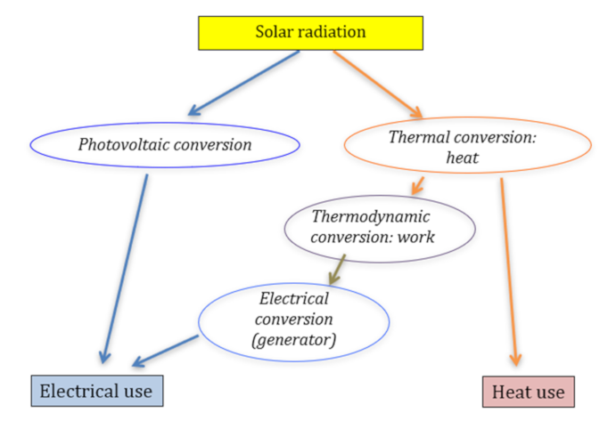
Figure 22. Conversion of solar energy.
In addition to the two modes of direct conversion (thermal and photovoltaic), we can use a cascade of conversion from heat: first conversion into work (mechanical energy) using thermodynamic cycles, we then speak of thermodynamic conversion (See: Thermodynamics: the laws), then conversion of this work into electrical energy using generators.
There are two ways of converting solar radiation into electricity: the photovoltaic way (direct) and the thermodynamic way (indirect), which consists of first converting the light energy into heat, then converting this heat into work and finally into electricity. This conversion of heat into electricity is the one used in all thermal power plants, including nuclear power plants (Read: Nuclear reactors).
Regarding the physical principles governing this conversion of heat into electricity, it is important to point out that obtaining a significant and interesting efficiency requires concentrating solar rays in order to obtain high temperatures from the hot source. The efficiency (known as Carnot’s efficiency) is in fact an increasing function with the difference in temperature between the hot source and the cold source (Read: A brief history of energy).
Notes and references
[1] Malherbe Jean-Marie (2010). Introduction to the physics of the Sun, Cours, Hal Archives-ouvertes.fr
[2] Forgan Bruce W. (2011). Solar Radiation Measurement, WMO RAV Metrology Workshop, Melbourne, November.
[3] Forgan Bruce W. (2011). Solar Radiation Measurement, WMO RAV Metrology Workshop, Melbourne, November.
[4] Blanc P. and others (2014). Direct normal irradiance related definitions and applications: The circumsolar issue. Solar Energy, 110 pp. 561-577.
[5] Kittel Charles (1998). Physics of the Solid State, Dunod.
[6] Spitz J. (1979). Selective materials for photothermal conversion of solar energy. Revue de Physique appliquée, volume 14, January.
[7] Sze Simon M. (2006). Semiconductor devices, physics and technology. London: Wiley.
The Encyclopedia of Energy is published by the Association des Encyclopédies de l’Environnement et de l’Énergie(www.a3e.fr), contractually linked to Grenoble Alpes University and Grenoble INP, and sponsored by the Academy of Sciences.
To cite this article, please mention the author’s name, the title of the article and its URL on the Encyclopedia of Energy website.
The articles of the Encyclopedia of Energy are made available under the terms of the license Creative Commons Attribution – Noncommercial – No Derivative Works 4.0 International.