


In the great debate on the safety of nuclear energy, the development of new technologies is one of the answers. Among them, molten salt reactors are of great interest.
The following helps to understand the ins and outs.Since the 1950s, many nuclear power reactors have been built (see: History of nuclear energy), most of whichare pressurized water reactors (see: Nuclear reactors). However, many other methods have been explored, some of which continue to be studied, such as molten salt reactors.
This article was originally published under the title “Les réacteurs à sels fondus”, written by Elsa MERLE, Axel LAUREAU and Daniel HEUER – Les réacteurs à sels fondus – Encyclopédie de l’énergie (encyclopedie-energie.org).
It was translated into English by Tigran Grigoryan, a first-year student in the LEA Master’s degree in Multilingual Specialized Translation at the Foreign Languages Department (University of Grenoble Alpes), under the supervision of André Dodeman. All these speakers are sincerely grateful
1. General remarks
Molten salt reactors (MSR) use liquid fuel circulating in the form of molten fluorides or chlorides. Nuclear heat, whether from fission or radioactivity, generated in the fuel is transmitted to another circuit usually containing another molten salt. A third circuit converts this heat into electricity.
1.1. Interest in liquid fuels
As early as the 1960s, engineers at Oak-Ridge National Laboratory (ORNL) in the United States identified the great potential of liquid fuels in terms of intrinsic safety and controllability when they are also used as a coolant (a fluid used to transport heat). These fuels have very interesting characteristics:
- The fission heat is deposited directly in the coolant and transported out of the core in a few seconds, whereas in a solid fuel, this heat must first be diffused through the fuel rods and their cladding before reaching the coolant. The disappearance of this delay allows the thermal counter-reactions to act very early, which efficiently stabilizes the reactor. This feature can be used to enable rapid power variations.
- During an artificially imposed large reactivity excursion, the power increases very quickly, which causes significant fuel heating. If the latter is liquid, it expands and part of the fuel leaves the high neutron flux zone through a channel leading to the overflow tank. The fuel then becomes more transparent to neutrons, which reduces the reactivity and brings the reactor back to its nominal state. Using numerical simulations, as well as feedback from a critical experimental liquid fuel reactor, it is shown that this effect makes a Chernobyl-type accident physically impossible. (see: Experience feedback of nuclear accidents).
- In an out-of-control situation simulated for safety studies, the liquid fuel can be evacuated from the reactor core in a few minutes by a simple gravity drain after the opening of a drain plug. This makes it possible to provide an emergency draining tank where the fuel can be passively cooled in complete safety. Therefore, a Fukushima-type situation can be managed without even requiring operator intervention, as the reactor automatically goes into standby mode and restarts within weeks or months after the event.
- The liquid state of the fuel allows withdrawals and additions without shutting down the reactor. In particular, it is possible to greatly reduce the built-in reactivity and thus eliminate any risk associated with such a reactivity that could be released suddenly and cause an accident.
- It is also not possible to inject reactivity by fuel densification since the liquids are incompressible.
- The liquid state of the fuel avoids having to build and deconstruct assemblies that can be fragile and complex to cool in the case of fuel multi-recycling.
- The use of minor actinides, currently considered as waste and vitrified although they can split and thus be used as fuel, could be simplified into a fuel that does not require the fabrication of pellets and assemblies.
- Finally, since the fuel is constantly stirred by passing through heat exchangers, it is homogeneous, which makes complex loading plans unnecessary, although they are indispensable with solid fuel. The built-in reactivity becomes useless, thus strongly limiting the possible initiators of an accident.
Nevertheless, all these characteristics are only potential. Only a careful choice of liquid type and reactor design can realize this potential.
1.2. Liquid selection
A good liquid must meet several criteria ranging from transparency to neutrons to the non-production of harmful radioisotopes, including sufficient solubility of the fertile and fissile elements, physicochemical properties suitable for heat evacuation, operational stability, fuel reprocessing and corrosion risk. It turns out that fluoride or chloride ionic salts are good candidates to meet these criteria, hence the name Molten Salt Reactor (MSR).
The inelastic neutron scattering spectra of fluorine has several resonances at energies of a few hundred keV, which greatly reduces the number of neutrons at these energies. As a result, the neutron flux is less energetic and induces much less damage to structural materials, which could prove to be a decisive advantage. However, this strongly penalizes the U-Pu cycle which needs these high energy neutrons to ensure a good regeneration of fissile nuclei. Fluorides are therefore more suitable for the Th-U cycle. In this case, the best solvent for about 22% actinides is LiF, they form a eutectic mixture with a 585°C melting point. Since 6Li has a very large neutron capture cross section while producing large amounts of tritium, it is necessary to use lithium isotope 7Li enriched to over 99.9%. This enrichment requires recycling of the lithium during fuel reprocessing.
Considering the other option, chlorides, natural chlorine contains 75.77% of 35Cl which produces, by neutron capture, radioactive 36Cl with a half-life of 301 000 years. As it is unrealistic to hope to store chlorine efficiently over such a long period of time, the use of chloride requires 37Cl enrichment of more than 99%,which, moreover, is much more transparent to neutrons than 35Cl. This enrichment requires the recycling of chlorine during the reprocessing of the fuel. Since the neutron spectrum generated by chlorides has a very large fast neutron component, chlorides are particularly suitable for the U-Pu cycle despite a significant impact on the structural materials. In this case, NaCl is the best solvent for 33% actinides with a melting temperature of 500°C. Operation at lower temperatures than in fluoride is therefore possible, which would allow the use of more conventional and validated materials such as steel 316. Chlorides are also good candidates for the incineration of plutonium or minor actinides because of their very hard neutron spectrum, which results in a higher ratio of fissions to captures for these nuclei. To do this, an ingredient such as MgCl2 can be added to the solvent in order to be able, by adapting the concentration of MgCl2, to simultaneously choose a volume of core and a proportion of plutonium or minor actinides.
1.3. The different concepts of MSRs
There is no single type of MSR, on the contrary, depending on the purpose sought, MSRs can be found in various configurations. This is made possible by the great flexibility of this type of reactor, both in terms of design and control. The possible choices concern the type of fuel, the type of neutron spectrum, the size of the core or the specific power[1]. What guides the choice depends on what is expected from the reactor. However, two main classes of reactors can be distinguished depending on whether a massive deployment or a niche market is targeted.
1.3.1. Large-scale deployment
If it is a question of producing energy on a massive scale at the world level and over a long period of time that can exceed a century, it is necessary to be attentive to the availability of fissile material. In this case, the fissile material will be regenerated from the only two available fertile materials, uranium-238 and thorium-232. However, during the first start-up of a new reactor it is necessary to load it with fissile material to reach criticality. Since the only naturally occurring fissile material is uranium-235, which makes up only 0.72% of natural uranium, and since the expected over-regeneration will never be very significant, it is necessary to limit the initial load of fissile material per unit of energy produced. This demands to look for the highest possible specific power, but a thermal neutron spectrum will also be favorable to the limitation of the initial load.
It is important to note that the regeneration of fissile material requires efficient fuel reprocessing to extract the produced fissile material and reject fission products.
If the choice is uranium-238, then only the chlorides in fast neutron spectrum are reasonably available. This choice allows affordable temperatures with conventional materials like steel316.
If thorium is chosen, it is preferable to opt for fluorides which greatly reduce damage to materials. Then thermal neutron spectrum is possible, but in this case poisoning due to fission products requires very frequent reprocessing of the fuel, which can be detrimental. In terms of materials, the Hastelloy-N, developed at the time, proved its effectiveness during the MSRE experiment conducted at ORNL in the 1960s.
In all cases, this massive deployment is possible both with power reactors capable of producing more than 1 GWe and small modular reactors (SMRs) of one to a few hundred MWe. This deployment can be initiated with plutonium and minor actinides produced by operating reactors, which makes it possible to reduce the amount of final waste (see: Small modular reactor-SMR).
1.3.2. Niche market
Niche markets are targeted to specific applications such as space exploration, burning of actinides from operating reactors, producing radioisotopes for medicine or power generation in isolated areas. So, saving fissile material is no longer a priority. Therefore, it will be possible to move towards small reactors with low specific power and simplified operation. For example, they would not require reprocessing over a relatively long period of time, up to several decades, which would make it possible to dissociate the problem of reactor operation from that of fuel reprocessing. The first demonstration molten salt reactors will obviously fall into this category.
1.4. History of MSRs
Two MSRs have already operated in the past at ORNL. In 1954, when the US Air Force wanted a nuclear-powered aircraft, a small 2.5 MWth molten salt reactor, called the Aircraft Reactor Experiment (ARE), was ground-tested for about 100 hours. This type of reactor was chosen because, in addition to being compact, its control is flexible and it allows for wide variations in power over short periods of time, which is essential for an aircraft. This test revealed that liquid nuclear fuel was relatively easy to implement, but the fluorinated salts used tended to corrode excessively the structural materials such as Inconel 600, which were in use at the time.
After the nuclear-powered aircraft project was stopped, the ORNL physicists began to improve their concept by building the Molten Salt Reactor Experiment (MSRE). The latter operated for five years with a rated output of 8 MWth. It had a thermal neutron spectrum thanks to a graphite matrix in which the molten salt circulated. The development of a nickel-based alloy, Hastelloy-N, resolved the corrosion problems. The MSRE was used with three different types of fissile material: enriched uranium, 233U and plutonium, but it has never contained enough fertile material to be regenerated, and in particular it has never been loaded with thorium. Power variation tests without a control rod were also successfully carried out on the MSRE, demonstrating in a real case the excellent load following capabilities of this type of reactor.
Following this successful experiment, the same ORNL physicists developed a concept paper on a power reactor for electricity production. This was the Molten Salt Breeder Reactor (MSBR). While this project was stopped in the United States, several countries resumed studies on MSR including France with the CEA and EDF.
In the early 2000s, in order to verify MSBR’s ability to participate in the fight against climate change, a CNRS team based at the Laboratory of Subatomic Physics and Cosmology (LPSC) in Grenoble undertook to re-evaluate it with modern computational methods and computer means. Probable prohibitive limitations then emerged:
- due to the large size of the reactor, the thermal feedback coefficients were not very good and especially the one related to fuel expansion was largely positive;
- the presence of a large quantity of graphite in the core led to fears of a serious fire in the event of an accident;
- fuelreprocessingto attain regeneration,around 4 m3 per day because of the chosen thermal neutron spectrum and the highest specific power, was significant and therefore unrealistic.
This highlighted the fact that while a liquid fuel has a high safety potential, this potential does not materialize automatically. It is necessary to pay close attention to the basic design. A systematic study of the possible MSR configurations has then shown that a fast neutron spectrum allows this potential to be materialized very well. The LPSC team then proposed a new concept based on the fast neutron spectrum, which was selected in 2008 by the GEN-IV International Forum Policy Group as the reference concept for MSR and named the Molten Salt Fast Reactor (MSFR).
2. The reference MSFR
Since 2011, MSFR research has been supported by the European Union (EU), which first established the Euratom Collaborative Evaluation and Viability of Liquid Fuel Reactors (EVOL) project with a budget of one million euros over three years to study MSFR in collaboration with the Rosatom Molten Actinides Recycling System (MARS) project. In 2015, the EU funded a four-year 3.5 million euro Safety Assessment of the Molten Salt Fast Reactor (SAMOFAR) project under the Horizon 2020 program to conduct a MSFR safety study. Then, at the end of 2019, a four-year European project SAMOSAFER worth 4 million euros began to study the functioning of MSFRs in severe accident situations.
The design described below, considered to be that of the reference MSFR, was the one adopted by all the French and European partners at the beginning of the SAMOFAR project with some modifications and additions resulting from the studies carried out during this project. It is a 3 GWth regenerative power reactor with a Thorium-Uranium (Th-U) fuel cycle.
The reactor comprises three main circuits, namely the fuel circuit entirely contained in the reactor vessel, the intermediate circuit circulating the cooling salt and comparable to the primary circuit of a solid fuel reactor, and the conversion circuit probably containing supercritical water or supercritical CO2 and making it possible to convert heat into electricity.
The reactor has two separate and redundant passive emergency cooling systems: the emergency cooling system and the emergency drain system.
2.1. Fuel circuit
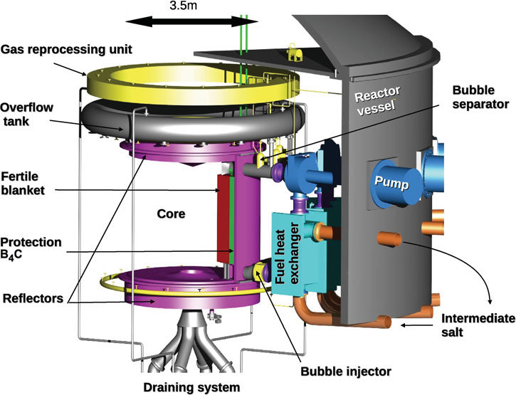
In conventional representations of MSRs, the liquid fuel exits the core and passes through heat exchangers and pumps before returning to the core. This configuration is problematic since there is a definite risk of fuel leakage one day, which is unacceptable. Then a design was proposed in which the fuel circuit is entirely confined in a vessel that is not subject to mechanical stress or excessive temperatures. The cooling sectors shown in Figure 1 are attached to the inner side of the vessel leaving free the central part, which contains 9 m3 of combustible salt and corresponds to the reactor core. These sectors mainly include a pump, a heat exchanger, a fertile blanket or a neutron reflector as well as a neutron protection to limit the neutron flux at the pump and the exchangers. These sectors are compact, making them easily transportable and replaceable if necessary (see Figure 1).
The vessel is closed by a sealed cover comprising a neutron reflector to protect the exterior and the main overflow tank is connected to each overflow tank of the pumps. Pump shafts are magnetically driven in order to avoid passing through the cover. A salt, called “intermediate”, enters the vessel to cool the heat exchangers, as well as the walls in contact with the combustible salt and the fertileblanket.
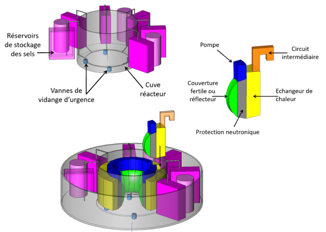
Fig. 1 : Integrated geometry of the MSFR including the reactor vessel and the cooling sectors. [Source: author]
| Réservoirs de stockage des sels | Salt storage tanks |
| Vannes de vidange d’urgence | Emergency drain valves |
| Cuve réacteur | Reactor vessel |
| Pompe | Pump |
| Couverture fertile ou réflecteur | Fertile blanket or reflector |
| Protection neutronique | Neutron shield |
| Circuit intermédiaire | Intermediate circuit |
| Echangeur de chaleur | Heat exchanger |
2.2. Emergency draining system
The vessel bottom is made of a thick reflector and it contains active and passive valve systems to allow emergency drainage of the fuel to the tank configured to contain all the fuel in a highly subcritical geometry and to evacuate passively the residual power[2] for short- and long-term safety of the system. This tank is reversible, it allows the recovery of the fuel to the normal storage tanks and the reboot of the core. In case of malfunction, this emergency draining tank is backed up by a core catcher playing the same role as a corium recuperator in a pressurized water reactor (PWR). Whether the combustible salt is in the emergency draining tank or in the core catcher, heat is removed passively by natural convection of air passing through the emergency heat exchangers (EHXs) as shown in Figure 2.
2.3. Emergency cooling system
Emergency draining is only planned in extremely unlikely situations. In all the accidental situations identified to date[3], the fuel can remain in the core thanks to a passive emergency cooling system based on the natural convection of the intermediate salt then confined in the reactor vault (see Figure 2). The system is not completely passive since in the event of a total loss of cooling, the valves V1a and V1b must be closed while the valve V2 must be opened. However, this system could prove reliable enough to do without the emergency draining tank and just rely on the core catcher, especially in small or simplified design reactors.
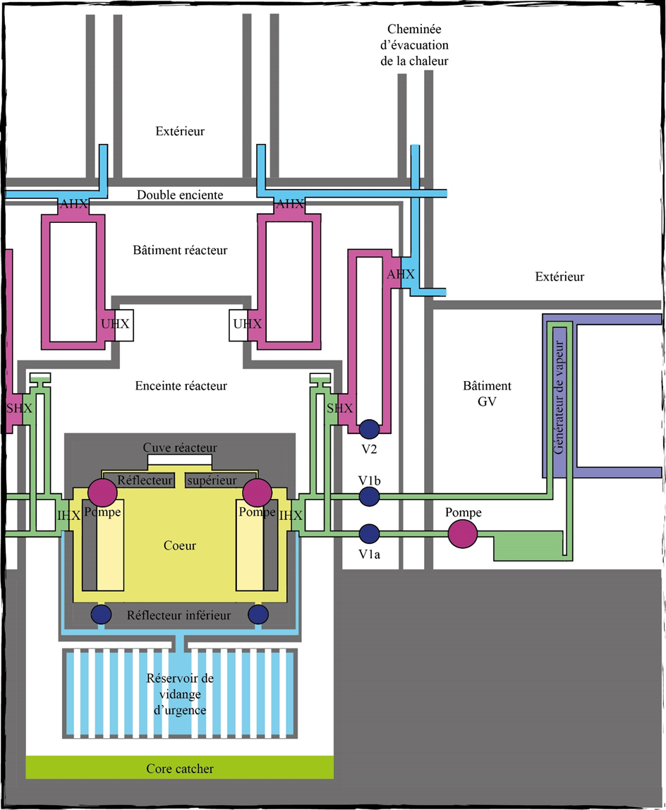
Fig. 2. Schematic view of emergency (EHX) and standby (SHX) cooling systems. The yellow circuit contains the fuel, the green circuit contains the intermediate salt and the red and blue circuits contain air. [Source: author]
| Extérieur | Exterior |
| Double enceinte | Double enclosure |
| Bâtiment réacteur | Reactor building |
| Enceinte réacteur | Reactor vault |
| Cuve réacteur | Reactor vessel |
| Pompe | Pump |
| Réflecteur supérieur | Upper reflector |
| Cœur | Core |
| Réflecteur inférieur | Lower reflector |
| Réservoir de vidange d’urgence | Emergency draining tank |
| Core catcher | Core catcher |
| Cheminée d’évacuation de la chaleur | Heat transfer chimney |
| Générateur de vapeur | Steam generator |
| Bâtiment GV | Building SG |
| V1a V1b V2 | V1a V1b V2 |
| AHX | AHX |
| IHX | IHX |
| SHX | SHX |
| UHX | EHX |
2.4. Confinement barriers
Figure 2 also provides an opportunity to visualize the various barriers separating the fuel and therefore radioactive materials from the external environment.
The first barrier consists of the reactor vessel and the intermediate heat exchanger (IHX) plates. To avoid breaking through this barrier, the pump shafts must be driven by a magnetic transmission. Compared to a solid fuel reactor, this barrier is the equivalent of the fuel cladding.
The second barrier is an enclosure containing the reactor vessel and the emergency draining tank if one exists. The core catcher is placed inside this barrier. The latter is pierced by the inlet-outlet of the intermediate fluid and is extended by the plates of the standby (SHX) and emergency (EHX) heat exchangers. Compared to a solid fuel reactor, this barrier is equivalent to the reactor vessel in which the corium catcher would have been installed.
The third barrier consists of two containment envelopes. The first, probably metallic, must be watertight but does not need to withstand a pressure increase. The second, probably made of concrete, serves as protection against external aggression.
2.5. Fine control
Since the fission energy is deposited directly in the coolant, a liquid fuel nuclear reactor can be driven directly by heat extraction, making any control rod unnecessary.
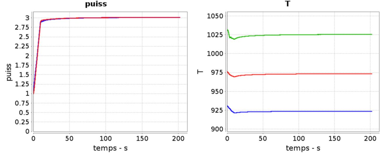
Fig. 3. Load tracking from 1 GWth to 3 GWth in 10 seconds. Left: evolution of the requested (red) and supplied (blue) powers. Right: evolution of the combustible salt temperatures at the exchanger inlet (green), at the exchanger outlet (blue) and average (red) [4].
In principle, if the requested power increases, the combustible salt is cooled which causes an increase in reactivity and therefore an increase in power and finally a return to the initial temperature with a higher fission power. This adjustment of the fission power with the external demand is done in a few seconds but leads to undesirable temperature variations in the heat exchangers. The solution consists in causing the power variation by modifying the flow rates of the fuel and intermediate circuits. The study of the normal and accidental operation of the MSFR has required the CNRS to develop simulation tools that are unique in the world, taking into account the physical phenomena specific to this type of circulating fuel reactor. Figure 3 shows the simulation of such load tracking for thermal power from 1 GWth to 3 GWth in ten seconds! This load-following flexibility, i.e. rapid modification of the power produced, has no effect on the integrity of the reactor. The limitation is therefore not at the core itself but at the energy conversion circuit. This would allow an excellent symbiosis in an energy mix with a high share of intermittent renewable energy sources (see: Electricity in the global energy balance: dynamics of evolution and interpretation).
2.6. Overcooling accident
The last few years have been largely devoted to the study of the safety and operation of the MSFR and more particularly to the investigation of a possible serious accident identified as a situation leading to a massive release of radioactivity into the environment (see: Nuclear safety).
Such a serious accident has not yet been identified and the most worrying situation that has been highlighted is a massive and brutal over-cooling of the fuel starting from a new combustible salt producing only 1 kWth energy through spontaneous fissions. It is assumed that the combustible salt is in nominal circulation, which is the worst case, while the intermediate salt is at a standstill. Following an operator error, the intermediate salt is put into nominal circulation in a very short time.
In Figure 4, at the top, the evolution of the temperature field is observed in the unrealistic hypothesis of an instantaneous transient. After four seconds, the temperatures have stabilized and the supplied power is 3 GWth. The bottom left side of Figure 4 shows the prompt criticality margin for different durations of this overcooling. If the transient is sufficiently short, the reactor goes into a mode called prompt critical. If the fuel were solid, this situation would lead to its destruction, and this is the type of power peak that occurred at Chernobyl. The instantaneous fission power in the core is represented at the center. A power peak of up to 20 GWth is indeed observed when the transient occurs in one or two seconds. However, on the right, the effect on temperatures is small enough that no mechanical effects are to be feared. The reactor is able to withstand this type of sudden variation without any cliff-edge effect, that is a violent change in core behavior with a change of regime, which is very important and positive from the point of view of nuclear safety analysis.
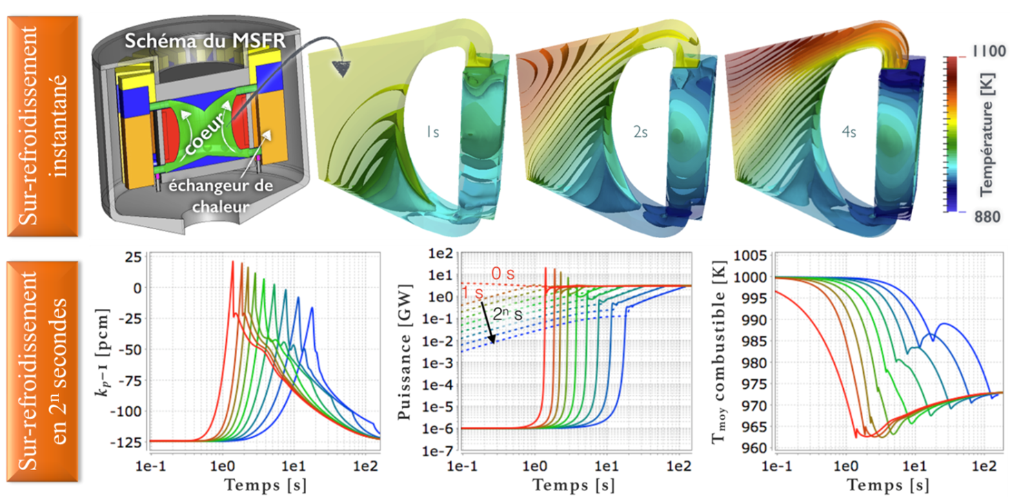
Fig. 4. Overcooling accident starting from a power of 1 kWth and leading to an output of 3 GWth. At the top, the temperature field in the core and a heat exchanger for an instantaneous transient. At the bottom, the prompt criticality margin, the power and thefuel average temperature during a transient lasting from 0 to 128 s [5].
| Sur-refroidissement instantané | Instant overcooling |
| Sur-refroidissement en 2n secondes | Overcooling in 2n seconds |
| Schéma du MSFR | MSFR schema |
| cœur | core |
| échangeur de chaleur | heat exchanger |
| Température [K] | Temperature [K] |
| Kp – I [pcm] | Kp – I [pcm] |
| Temps [s] | Time [s] |
| Puissance [GW] | Power [GW] |
| Tmoy combustible [K] | Fuel average temperature [K] |
Of course, these are numerical simulations, but this behavior of liquid fuels is already well known and experimental reactors have in the past used this capability to carry out criticality accident studies. For example, the SILENE reactor at the CEA/Valduc Center made it possible to produce power peaks regularly and in a deliberate and controlled manner by rapid over-criticality in a liquid fuel reactor.
3. Molten salt reactors in the world and their prospects
After developments mainly in the United States in the 1950s to 1970s, molten salt reactors were the subject of occasional prospective studies in the 1990s in Russia, France and Japan, in particular, without being followed by dedicated research programs. When the CNRS entered the field of nuclear power as a result of the Bataille’s Law, shortly before 2000, researchers from the LPSC Grenoble have taken up the subject as mentioned above and have resumed studies on molten salt reactors, using, on the one hand, modern computational resources, and on the other hand, using a more academic approach, i.e. more systemic and prospective, in order to define scientifically acceptable configurations from the point of view of reactor physics and chemistry. This led to the development of the so-called reference MSFR, an optimized version of these acceptable configurations as a regenerative Thorium cycle reactor. The MSFR reference reactor has since been studied under European (EVOL, SAMOFAR, SAMOSAFER) and national (NEEDS challenge in France, in particular) programs.
Studies are continuing on MSRs at CNRS/IN2P3 and are now targeting alternative versions (U/Pu cycle regenerator, SMR, incinerator, among others) still with this philosophy of systemic and prospective research, based on science (physics and chemistry) and societal acceptability, also in support of more industrial approaches carried out by CEA, ORANO and Framatome, which are showing a new and increasing interest in MSRs.
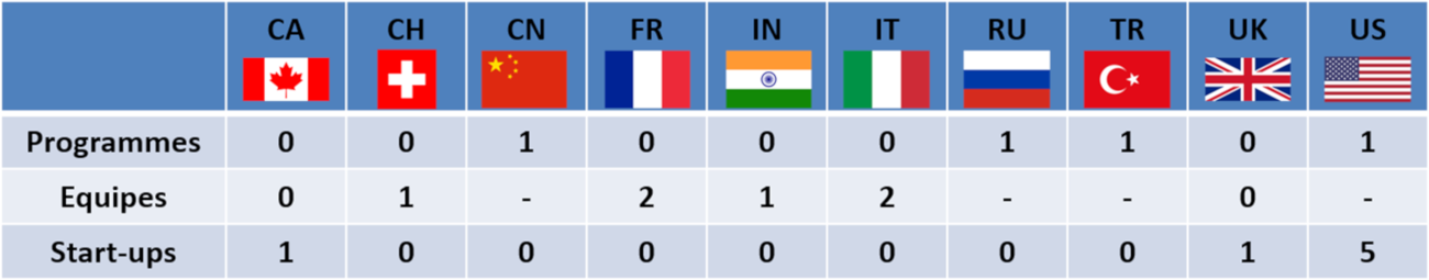
Fig. 5. Summary of national research activities on molten salt reactors in the world. [Source: author]
| Programmes | Programs |
| Equipes | Teams |
| Start-ups | Startups |
This national interest is motivated in part by the strongly growing interest at the global level, as can be seen in Figure 5. Thus, the MSR Steering Committee of the Generation IV Forum, initially made up of France and Euratom, now also includes Russia, the United States, Switzerland and China, plus Japan and Korea as observers. Since 2016, the International Atomic Energy Agency (IAEA) has hosted a global workshop to reflect on and take stock of the state of MSR technology, in which sixteen IAEA member countries have expressed their willingness to participate. Substantial research programs have been launched on the subject in China (SINAP laboratory of Shanghai Institute of Applied Physics, the construction of a demonstrator was initiated in 2019); in the United States the funding of several million dollars by the Department of Energy (DoE) for the MCFR project piloted by Terra Power, and in Russia, a Rosatom-funded incinerator project. Finally, a significant number of startups (United States, United Kingdom, Canada) are developing to offer various variants of MSR.
March 2023 update: to go further on molten salt reactors and SMRs, a paper by Michel Belakhovsky on the state of this sector in February2023: http://confrontations.org/wp-content/uploads/2023/03/Les-reacteurs-nucleaires-SMR-dans-le-monde-Entre-engouements-et-realites-Michel-Belakhovsky-1.pdf
Notes et références
[1] The specific power is the thermal power per unit volume of fuel
[2] The residual power is the energy produced by the radioactivity of the fuel when the chain reaction is stopped
[3] Gérardin D. Doctoral thesis, 2018
[4] Laureau A. Doctoral thesis, 2015
[5] Laureau A. Doctoral thesis, 2015