
Limited to space applications in the last century, fuel cells are now invading all sectors of activity: transport with on-board batteries, businesses and homes with stationary batteries, and everyday life with miniaturized batteries. But what is a fuel cell? Two eminent specialists provide the answer.
The fuel cell concept has been known since the beginning of the 19th century, but it was during the second half of the 20th century that scientific and technological advances considerably increased its performance and opened up new industrial perspectives.
1. The fuel cell, an open electrochemical generator
We use closed generators (alternators, engines) on a daily basis, which is precisely what fuel cells are not, as they are open generators.
1.1. What is an electrochemical generator?
The fuel cell is an electrochemical generator that converts the energy stored in the chemical bonds of compounds (called oxidizing: able to receive electrons by reducing, and reducing: able to lose electrons by oxidizing) into electrical energy and heat. This transformation of matter into electrical energy is only possible for spontaneous reactions, i.e. reactions that can release energy in the sense of thermodynamics; in other words, if the chemical bonds of the reactants contain more energy than those of the products, then the transformation of the reactants into products is irreversible. The speed at which this transformation takes place is nevertheless variable and depends on the activation barrier of the reaction considered: it can be infinitely fast (e.g. explosion), or slow (e.g. corrosion of iron at room temperature) depending on the experimental conditions (concentrations, temperature, pressure, etc.). This transformation, if it takes place by direct reaction of the oxidant on the reductant, releases energy in the form of heat, which can then be converted into mechanical form (this is the case of thermal machines) or electrical form; in this case, the efficiency of the energy conversion is limited by the Carnot cycle [1] (cf. 3.1. Thermodynamic advantages of fuel cells).
The interest of electrochemical generators is precisely to avoid direct contact between the oxidant and the reductant: separating them by a medium allowing the conduction of ionic charges but incompatible with electronic conduction (the electrolyte) makes it possible to use electrical energy on demand. Indeed, the electrons coming from the oxidation reaction and used by the reduction reaction can then pass through an electric circuit outside the generator. This circuit is maintained in an open (Figure 1(A)) or closed (Figure 1(B)) position by the user, who decides whether or not to pass the electrical charges. The direct conversion of chemical energy into electrical energy is thermodynamically more efficient than the thermal route (Carnot type), but depends on the kinetics of the processes involved (see below) [1, 2]. It is based on controlled electrochemical reactions, taking place at the interfaces between each of the two electrodes (the one containing the oxidant and the other containing the reductant) and the electrolyte separating them physically. As such, electrochemical generators are heterogeneous (electro)chemical reactors. Their performances depend on the nature of the materials used, but also on their shaping; the necessary processes of charge transfer (i.e. the electrochemical reactions which allow the generation of electric current) are associated with processes of material transport, which are no less necessary, because only the active material present at the interfaces (electrode | electrolyte) will be able to be used. It is therefore understandable that the dimensioning and operation of electrochemical generators is not trivial; it will be highlighted in section 4. Proton Exchange Membrane Fuel Cell (PEMFC) technology.
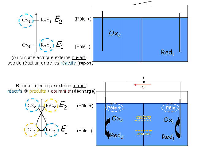
Figure 1: In discharge, the charge flow is continuous on the generator + external circuit; in the electrolyte, this charge flow is carried by the ions (cations migrating towards the cathode, i.e. the electrode where reduction takes place: positive electrode in discharge and anions migrating towards the anode, i.e the electrode where oxidation takes place: negative electrode in discharge).
1.2. The fuel cell: an open electrochemical generator
 fermé (les matériaux actifs sont contenus dans le générateur – une fois consommés, ils doivent être rechargés électriquement) ou (B) ouvert (le combustible et l’oxydant peuvent être approvisionnés en continu durant le fonctionnement).")
Among the many types of electrochemical generators, some contain the active material (energy source) and are therefore energy storage and conversion systems. This is the case of batteries and accumulators [2, 3], also called closed electrochemical generators (Figure 2(A)). Supercapacitors also fall into this family of generators, although strictly speaking, they do not involve electrochemical reactions [4]. When the reagents are consumed, these systems must be recycled (batteries) or recharged (accumulators). They are therefore intrinsically limited in energy density: for example, lithium batteries, the most efficient of them, do not exhibit practical energy densities higher than ca. 200 Wh kg-1 (related to the system mass [5]).
The technology of open electrochemical generators (in the forefront of which are the fuel cells: PAC, Figure 2(B)) makes it possible to overcome these energy density deficiencies. In this case, the generator is supplied during its use by means of tanks for the fuel (reducer) and the oxidizer (oxidant), whose adequate dimensioning or the frequency of filling makes it possible to adapt the autonomy of the system; a continuous discharge (stationary) is even possible, contrary to the case of closed generators. These properties give the PACs much higher energy densities than closed electrochemical generators.
To make possible its supply, the fuel must be gaseous (typically: dihydrogen, H2) or liquid (e.g. light alcohols) or in solution (e.g. NaBH4 dissolved in water at basic pH). For the oxidizer, it is the same (e.g. gaseous O2 or liquid hydrogen peroxide); moreover, the oxidizer is often dioxygen directly taken from the ambient air and is thus not to be stored.
2. The different types of fuel cells
Discovered in principle as early as 1802 by Sir Davy [6], fuel cells remained laboratory curiosities between their first practical application in the laboratory by Sir Grove in 1839 [7] and the work of Bacon in the 1940s and 50s, which led to the first power system (6 kW) [8]. Nevertheless, the work of the latter inspired the engineers of NASA (National Aeronautics and Space Administration, i.e. the national administration of aeronautics and space of the United States of America), which made fuel cells the electrical generators of all their Gemini and Apollo missions, then of those of the shuttles (Shuttle missions) until the 2000s [8]. These applications, the first for systems considered too expensive and, at the time, uncompetitive in terms of power density, showed that fuel cells were very relevant generators in terms of energy density and efficiency in converting chemical energy into electrical energy.
2.1. The thermodynamic advantages of fuel cells
The higher energy density of fuel cells compared to closed electrochemical generators comes from the spatial dissociation of the “storage” (reservoir) and “conversion” (cell core) functions, but also from the fact that the oxidant is generally taken from the air. The PAC are also interesting compared to other types of open generators such as thermal machines. Indeed, the maximum theoretical efficiency of a thermal machine, given by Carnot’s theorem [1] :
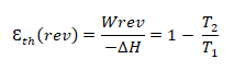
is usually less than 30% for internal combustion engines (up to 40% for a gas turbine), because the maximum temperature of stability of the engine materials is not scalable at will (with εth (rev) $${epsilon^{Thermal}_{rev}}$$ the theoretical (reversible) efficiency of the thermal machine, Wrev the reversible mechanical work, ΔH the enthalpy of reaction and T2 | T1 the ratio of the absolute operating temperatures of the machine).
A fuel cell using the same fuel/oxidant couple under reversible conditions, at constant temperature and pressure, has a thermodynamic efficiency:
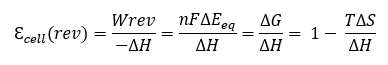
with εfc (rev) $${epsilon^{Pile}_{rev}}$$ the theoretical (reversible) efficiency of the fuel cell, We the reversible electrical work, ΔG, ΔS, ΔEeq the free enthalpy, entropy and electromotive force of the cell (difference of the thermodynamic potentials of the two half-reactions occurring at the electrodes), n the number of electrons involved and F the Faraday constant. For example, εcell (rev) $${epsilon^{Cell}_{rev}}$$ is 83% for H2 fuel (at 298 K).
In practice, the efficiency of a fuel cell depends on the current it delivers, due to kinetic limitations. The first one concerns the faradic efficiency Qf i.e. the propensity of the reaction to use efficiently all the fuel; contrary to the case of closed generators, where Qf is in practice much lower than the unit, the gaseous or liquid character of the fuel makes that one really approaches Qf = 100 %, if necessary, by means of a fuel recirculation. The second limitation comes from the kinetics of charge transfer and material transport to the interface; it will be detailed in Section 4.3. PEMFC performance and durability.
2.2 Implications for operating temperature, constituent materials and fuel selection
Since their discovery, many fuel cell systems have been studied in the laboratory, developed at the (pre)industrial level and tested on site. If all of them allow to convert a fuel into electrical energy, through an electrochemical reaction with an oxidant, this conversion is possible at different temperatures and with different materials (electrocatalysts and electrolyte). This allows the distinction of several families of fuel cells, generally thanks to their operating temperature, the nature of their core materials as well as the nature of the reagents that can reasonably be used in them. Table 1 summarizes the main families of fuel cells.
Table 1: the different families of fuel cells.
|
Name
|
Electrolyte
|
Catalyst type
|
Temperature
operating temperature
|
Development level
|
|
|
Anode
|
Cathode
|
||||
|
AFC
|
KOH
|
Pt or non-noble metals
|
Pt or non-noble metals
|
< 353 K
|
Niche production
|
|
AEMFC
|
Alkaline polymer (OH-)
|
Pt or non-noble metals
|
Pt or non-noble metals
|
< 353 K
|
Research
|
|
PEMFC
|
Acidic polymer (H+)
|
Pt and alloys
|
Pt and alloys
|
< 373 K
|
Commercial
|
|
PAFC
|
H3PO4
|
Pt
|
Pt
|
473 K
|
Stopped production
|
|
MCFC
|
Li2CO3/ K2CO3
|
Ni
|
Lithiated Ni
|
923 K
|
Prototypes
|
|
SOFC
|
ZrO2-Y2O3
|
Ni
|
Perovskite (ABO3)
|
973 – 1273 K
|
Prototypes
|
AFC = Alkaline Fuel Cell
EAMFC = Anion Exchange Membrane Fuel Cell
PEMFC = Proton Exchange Membrane Fuel Cell
PAFC = Phosphoric Acid Fuel Cell
MCFC = Molten carbonate Fuel Cell
SOFC = Solid Oxide Fuel Cell
At first sight, all these PAC are likely to work with complex fuels, reformate gas (mixture of dihydrogen and carbon monoxide: H2 + CO) or dihydrogen, the easiest solution to implement, although the storage of H2 remains a real problem.Nevertheless, the direct oxidation of complex fuels (such as methane: CH4, or light alcohols) remains difficult, even at high temperature (e.g. problem of coke formation on the anodes of SOFCs valorizing methane [1]; slow oxidation reactions of small organic molecules in PEMFCs: DMFC [1]). Finally, the hope of being able to valorize complex fuels, both dense in energy and easier to store than H2, may come from AEMFCs, which would thus take advantage of the greater kinetics of such reactions as well as the stability of interesting compounds (e.g. NaBH4 [9]; N2H4,H2O[10]) in alkaline media [8, 11]. As far as the oxidant is concerned, apart from a few specific applications (e.g. submarines or spacecrafts, which can be supplied with an aqueous solution of H2O2 or bottled/liquid O2, respectively), it is the oxygen in the air that is more relevant to use, as it is abundant, free of charge and does not require any storage device, thus simplifying the PAC system.
Among these families, we distinguish the PAC whose technological progress is mature: thus the AFC were used successfully in the space conquest and several hundreds of PAFC allowed to produce electricity and heat (in cogeneration) in Europe, in the United States and in Japan. Despite these successes, these technologies are no longer relevant because they use noble metals (Pt) as catalysts in too large quantities and are unsuitable for mass production [8, 11].
Others, on the contrary, are attractive in terms of performance, but difficult to implement in practice, because their high operating temperature leads to significant instability of materials and assemblies; MCFC and SOFC therefore remain at the stage of technological research [8, 11].
Therefore, to date, only the PACs operating with an electrolyte membrane at an operating temperature close to room temperature can be considered for a large-scale deployment in the short term. As far as AEMFCs are concerned, their interest lies in the possibility of using more abundant and less expensive electrocatalyst materials than PEMFCs and the possibility of directly oxidizing a complex fuel (which is more difficult for a PEMFC), but there is still a lot of research and development work to be done before seeing these systems become established. Finally, only PEMFCs are being seriously considered by industrialists and are beginning to be commercialized to supply electrical energy to forklifts [12, 13], some isolated sites [14], or homes (the heat produced by the PEMFC being used for heating) [15]. It is on these systems that the remainder of this article will be based, to detail the operation as well as the advantages and disadvantages of the PAC.
3. Proton Exchange Membrane Fuel Cell (PEMFC) Technology
Among the various fuel cell systems, the PEMFC (proton exchange membrane fuel cell) are of particular interest.
3.1. The PEMFC system and its annexes
Like other fuel cells, a PEMFC is an open electrochemical generator. As such, a PEMFC cannot operate alone; it must be integrated within a system, comprising a certain number of devices called “annexes”. Figure 3 gives an exploded view of a PEMFC system as produced by Axane; it contains a frame on which the fuel cell stack and the annexes are fixed. The oxidant (O2) being drawn from the air, the PEMFC system must be able to filter and compress it (air compressor), humidify it (humidifier) and distribute it (gas distribution). The electrical power generated by the PEMFC must be converted according to the needs of the user (power electronics, conversion), a battery of accumulator being added to the PEMFC to supply the appendices at the starting and extinction of the system, this battery being recharged and maintained in load by the PEMFC when this last one functions. All these annexes are managed by an auxiliary command and control system. Of course, to these devices, it is necessary to add the fuel tank, whose size or frequency of filling will determine the autonomy of the PEMFC system. The heart of this cell system is the stack, itself composed of membrane-electrode assemblies, which are connected together by bipolar plates (see 4.2. From the membrane-electrode assembly to the stack: the heart of the PEMFC).
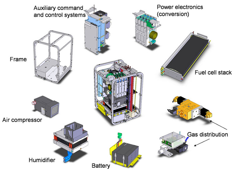
Figure 3: PEMFC system components. [Source: Axane]
3.2. From the membrane-electrode assembly to the stack: the heart of the PEMFC
The electrode reactions (electrooxidation of dihydrogen – blue reaction in Figure 4; electroreduction of dioxygen – blue in Figure 4) occur on Pt-based electrocatalysts. Ultimately, a PEMFC elementary cell leads to the formation of water: H2 + ½ O2 →H2O, which occurs at a theoretical cell voltage of 1.23 V under standard conditions. In practice, kinetic limitations lead to a non-negligible decrease of the cell voltage (cf.4.3. PEMFC performances and durability) and makes it necessary to assemble several elementary cells in series (by means of bipolar plates) in order to obtain a voltage that can be used in terms of electrical engineering.
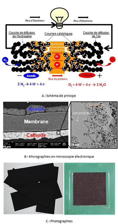
Figure 4: (A) Schematic diagram of the operation, constituents and electrode reactions of a PEMFC membrane electrode assembly (MEA). The black circles represent the carbon black, the small grey dots the Pt nanoparticles, the orange phase the ionomer and the membrane, the white background the porosity necessary for material transport. (B) Scanning electron microscopy (SEM) micrographs of an AME section and transmission electron microscopy (TEM) of active layer materials. (C) Photographs of gas diffusion electrodes and a commercial MEA.
State of the art electrocatalysts are based on platinum or its alloys with transition metals (Co, Ni, Cu). Due to their high intrinsic cost and low metal abundance, they are dispersed as nanoparticles on a conductive substrate of large surface area (usually carbon black). This allows (i) to increase the surface area (reaction site) to volume ratio (metal cost), (ii) to distribute the reaction volume over a volume (catalytic layers are typically about 10 µm thick), and to improve the conversion rate of reactants per cm2 of electrode, (iii) while distributing the ionomer (polymer of the proton exchange membrane, allowing the access of protons within the catalytic layers) and to maintain a sufficient porosity for the access of gaseous reactants and the evacuation of reaction products (water from the cathodic reaction, nitrogen from the air) This complex structure is based on the existence of percolating paths (i) for the electrons from the current collectors (bipolar plates), via the diffusion layers and up to the active layers, (ii) for the ions (protons) from the anode catalytic layer through the membrane and up to the cathode catalytic layer and finally (iii) of porosity for the access of the reactants and the evacuation of the products.
The membrane ensures multiple properties: barrier to the reactants (to avoid their mixing and thus any direct reaction which would not allow the generation of electric current) and to the electrons (to avoid any internal short-circuit, it must allow the passage of charges (protons) and thus a continuous flow of current on the whole (PAC + external circuit)). The diffusion layers must supply the active layers with reagent while eliminating the reaction products (notably liquid water); they must therefore be hydrophobic and porous. Finally, the bipolar plates must interconnect the adjacent elementary cells, and as such have a very good electrical conductivity (in their volume and in terms of contact resistance with the diffusion layer materials), be mechanically and (electro)chemically resistant to the aggressive environment of a PEFMC. They must also supply the reagents as homogeneously as possible over the entire geometric surface of the diffusion layers, which is usually done by means of millimeter channels etched/machined/molded/shaped into their surface.
From its core to the outside, the MEA is thus a stack of nanostructured layers with very specific electrocatalytic, material and charge transport properties. Thus, the catalytic layers ensure these three functions; the diffusion layers ensure the transport of matter (reactants and products) and the electronic conduction from/to the bipolar plates, the latter ensuring the interconnection from one elementary cell (core) to the other.
3.3. Performance and durability of PEMFCs
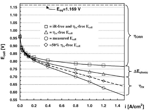
Figure 5: Typical electrical performance of a PEMFC single cell – Source: H.A. Gasteiger, S.S. Kocha, B. Sompalli, et al., Activity benchmarks and requirements for Pt, Pt-alloy, and non-Pt oxygen reduction catalysts for PEMFCs, Appl. Catal. B: Environmental, 56 (2005) 9., courtesy Elsevier.
The performance of a PEMFC system depends on the performance of the stack, which in turn depends on the performance of the elementary cells, but also on the performance of the annexes. By extension, the performances of a PEMFC elementary cell are determined by the materials composing it (membrane, electrocatalysts), but also by their architecture and assembly (catalytic layers, diffusion layers, membrane-electrodes assembly, etc.). Building a high-performance PEMFC system is therefore extremely complex and requires extensive work between specialists in materials (polymers, carbonaceous materials, electrocatalysts), assemblies (ink rheology, thin films, etc.), mechanical engineering and engineering. This explains the very long induction period between the discovery of PACs (in the middle of the 19th century) and their commercial deployment (which is just beginning for PEMFCs since the beginning of the 21st century).
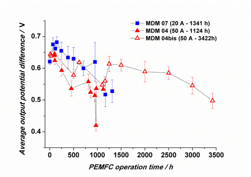
Figure 6: Example of evolution of the electrical performance of a stack of 16 cells (average voltage per cell according to the operating time in PEMFC, in different operating regimes).
In concrete terms, the apparent performance of a PEMFC single cell reflects this complexity. Thus, a single-cell polarization curve (Figure 1), i.e. the cell potential at a current density (o, this density being expressed in geometric A cm-2 of electrode) deviates significantly from the value predicted by thermodynamics (Eeq, – – – – -). Kinetic limitations are responsible for this deviation, which leads to a decrease in the practical efficiency of chemical-to-electrical energy conversion, as already mentioned in Section 3.1. Thermodynamic advantages of fuel cells.
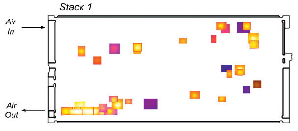
Fig. 7: (A) SEM image of a hole in a PEMFC membrane after operation and (B) mapping of the average location of holes within an assembly of 55 cells at the end of their life – Source: G. De Moor, C. Bas, N. Charvin, E. Moukheiber, et al., Understanding Membrane Failure in PEMFC: Comparison of Diagnostic Tools at Different Observation Scales, Fuel Cells, 12 (2012) 356. Courtesy of Wiley.
They manifest as overpotential (voltage losses) that have several origins: the low kinetics of oxygen reduction at the cathode (ηORR, *), ohmic losses in the membrane, electrodes, and at the interfaces (rEohmic , r), and losses related to insufficient material transport rate (ηtx, —¸—). Each of these losses can be addressed through work on PEMFC core materials and assemblies [18, 19].
In addition, the performance of PEMFCs decreases over time (see the example in Figure 6), as materials and assemblies degrade, ultimately leading to decreased electrical performance of the cells, and even to the end of the system’s life, often because the membrane is breached (Figure 7). The degradation mechanisms of PEMFC materials are extremely complex and extensively studied in the literature [16, 20-30].
3.4. Some examples of industrial applications
PEMFC activity is intense worldwide, but also in France and in particular in the Grenoble region. Thus, three industrial actors of PEMFC are located in the Grenoble area.
In chronological order of start-up, Axane, a subsidiary of Air Liquide, has been active for about 20 years in the field of 0.5 to 5 kW PEMFC systems for stationary applications (standby, generator, stabilized power supply). Its systems have notably been deployed to power telecommunication relays.
On a smaller scale in terms of the power of the systems produced, the company Paxitech commercializes PEMFC components (membrane electrode assemblies, unit cells) as well as small systems for nomadic applications that operate under breathing, i.e. without the need for the appendages mentioned in 4.1. The PEMFC system and its annexes.
Finally, Symbio, a CEA spin-off, designs range extender systems for electric vehicles. These three examples show that PEMFCs are now able to meet consumer expectations and that these systems are becoming a technological and commercial reality.
4. Conclusions
Fuel cells are open generators that complement well the offer of closed generators that we all use. Their open character gives them a higher energy density than their competitors, but also a degree of complexity that is undeniably more marked. Among the different families of PACs, PEMFCs are by far the most mature technology. After decades of research and technological improvements, these systems have achieved satisfactory initial performance, increased durability and steadily improving reliability, which now make them suitable for industrial deployment (Read: Hydrogen-powered hybrid vehicles and Storage of renewable energy in the form of hydrogen for isolated sites).
5. Acknowledgements
We thank the ANR and OSEO for their funding of our research. The companies Axane and Paxitech, as well as our colleagues from the LEPMI EI and LMOPS teams, and those from LEMTA have also greatly contributed to the quality scientific exchanges that have brought us to this point; for this, we thank them.
On a personal basis, MC warmly thanks S. Rosini and M. Billy for their ideas of illustrations, as well as the IUF for its support.
Notes and references
[1] M. Cassir, P. Stevens, F. Novel-Cattin, A. Hammou, C. Lamy, Piles à combustible, in: Techniques de l’ingénieur Accumulateurs d’énergie, vol. base documentaire : TIB243DUO, Editions T.I., 2000, pp. d3340.
[2] C. Sarrazin, Piles électriques Présentation générale, in: Techniques de l’ingénieur Accumulateurs d’énergie, vol. base documentaire : TIB243DUO, Editions T.I., 2001, pp. d3320.
[3] A. Jean, R. Jack, Accumulators Theoretical considerations, in: Techniques de l’ingénieur Accumulateurs d’énergie, vol. base documentaire : TIB243DUO, Editions T.I., 2004, pp. d3351.
[4] J.-C. Lassègues, Supercapacitors, in: Techniques de l’ingénieur Accumulateurs d’énergie, vol. base documentaire : TIB243DUO, Editions T.I., 2001, pp. d3334.
[5] A. Jean, R. Jack, Accumulators Lithium batteries, in: Techniques de l’ingénieur Accumulateurs d’énergie, vol. base documentaire : TIB243DUO, Editions T.I., 2005, pp. d3354.
[6] H. Davy, Nicholson’s Journal of Natural Philosophy, 1 (1802) 144.
[7] W.R. Grove, On Voltaic series and the combination of gases by platinum, Philosophical Magazine, 14 (1839) 127.
[8] W. Vielstich, A. Lamm, H.A. Gasteiger, Handbook of Fuel Cells, Wiley, Chichester, 2003.
[9] M. Chatenet, B.M. Concha, G. Parrour, J.-P. Diard, F.H.B. Lima, E.A. Ticianelli, Potential and limitation of the direct borohydride fuel cell. special emphasis on the borohydride oxidation reaction (bor) mechanism and kinetics on gold electrocatalysts, in: U.B. Demirci, P. Miele (Eds.) Boron Hydrides High Potential Hydrogen Storage Material, Nova Science Publishers, Inc, New York, 2010.
[10] K. Asazawa, K. Yamada, H. Tanaka, A. Oka, M. Taniguchi, T. Kobayashi, A platinum-free zero-carbon-emission easy fuelling direct hydrazine fuel cell for vehicles, Angewandte Chemie, International Edition, 46 (2007) 8024.
[11] H.A. Gasteiger, W. Vielstich, H. Yokokawa, Handbook of Fuel Cells, John Wiley & Sons Ltd, Chichester, 2009.
[12] Clean-Energy-Now, 2014-02-10
[13] V.P. McConnell, Fuel cells in forklifts extend commercial reach, Fuel Cells Bulletin, 2010 (2010) 12.
[14] E. Claude, The fuel cell: an industrial reality, in: CNRS (Ed.) GDR PACS, November 28, 2012.
[15] K. Maeda, M. Suzuki, H. Aki, R&D and deployment of residential fuel cell cogeneration systems in Japan, in: Power and Energy Society General Meeting – Conversion and Delivery of Electrical Energy in the 21st Century IEEE Xplore, Pittsburg, USA, 2008.
[16] L. Dubau, L. Castanheira, F. Maillard, M. Chatenet, O. Lottin, G. Maranzana, J. Dillet, A. Lamibrac, J.-C. Perrin, E. Moukheiber, A. ElKaddouri, G. De Moor, C. Bas, L. Flandin, N. Caqué, A review of PEM fuel cell durability: materials degradation, local heterogeneities of aging and possible mitigation strategies, Wiley Interdisciplinary Reviews: Energy and Environment, 3 (2014) in press.
[17] http://www.paxitech.com, 01/06/2014
[18] H.A. Gasteiger, S.S. Kocha, B. Sompalli, F.T. Wagner, Activity benchmarks and requirements for Pt, Pt-alloy, and non-Pt oxygen reduction catalysts for PEMFCs, Appl. Catal. B: Environmental, 56 (2005) 9.
[19] M. Chatenet, L. Dubau, N. Job, F. Maillard, The (electro)catalyst | membrane interface in the Proton Exchange Membrane Fuel Cell: similarities and differences with non-electrochemical Catalytic Membrane Reactors, Catal. Today, 156 (2010) 76.
[20] E. Guilminot, A. Corcella, M. Chatenet, F. Maillard, F. Charlot, G. Berthome, C. Iojoiu, J.-Y. Sanchez, E. Rossinot, E. Claude, Membrane and Active Layer Degradation upon PEMFC Steady-State Operation, J. Electrochem. Soc. 154 (2007) B1106.
[21] C. Iojoiu, E. Guilminot, F. Maillard, M. Chatenet, J.-Y. Sanchez, E. Claude, E. Rossinot, Membrane and Active Layer Degradation Following PEMFC Steady-State Operation, J. Electrochem. Soc. 154 (2007) B1115.
[22] C. Bas, L. Reymond, A.S. Danerol, N.D. Alberola, E. Rossinot, L. Flandin, Key Counter Ion Parameters Governing Polluted Nafion Membrane Properties, J. Polym. Sci, Part B: Polym. Phys, 47 (2009) 1381.
[23] C. Bas, L. Flandin, A.S. Danero, E. Claude, E. Rossinot, N.D. Alberola, Changes in the Chemical Structure and Properties of a Perfluorosulfonated Acid Membrane Induced by Fuel-Cell Operation, J. Appl. Polym. Sci. 117 (2010) 2121.
[24] L. Dubau, F. Maillard, M. Chatenet, J. André, E. Rossinot, Nanoscale compositional changes and modification of the surface reactivity of Pt3Co/C nanoparticles during proton-exchange membrane fuel cell operation, Electrochim. Acta, 56 (2010) 776.
[25] L. Dubau, F. Maillard, M. Chatenet, L. Guetaz, J. Andre, E. Rossinot, Durability of Pt3Co/C Cathodes in a 16 Cell PEMFC Stack: Macro/Microstructural Changes and Degradation Mechanisms, J. Electrochem. Soc. 157 (2010) B1887.
[26] G. De Moor, C. Bas, F. Lesage, A.S. Danerol, E. Claude, E. Rossinot, M. Paris, L. Flandin, N.D. Alberola, Understanding the Degradation of MEA in PEMFC: Definition of Structural Markers and Comparison Between Laboratory and On-Site Ageing, J. Appl. Polym. Sci, 120 (2011) 3501.
[27] L. Dubau, J. Durst, F. Maillard, L. Guétaz, M. Chatenet, J. André, E. Rossinot, Further insights into the durability of Pt3Co/C electrocatalysts: Formation of “hollow” Pt nanoparticles induced by the Kirkendall effect, Electrochim. Acta, 56 (2011) 10658.
[28] G. De Moor, C. Bas, N. Charvin, E. Moukheiber, F. Niepceron, N. Breilly, J. Andre, E. Rossinot, E. Claude, N.D. Alberola, L. Flandin, Understanding Membrane Failure in PEMFC: Comparison of Diagnostic Tools at Different Observation Scales, Fuel Cells, 12 (2012) 356.
[29] L. Dubau, J. Durst, F. Maillard, M. Chatenet, L. Guétaz, J. André, E. Rossinot, Heterogeneities of aging within a PEMFC MEA, Fuel Cells, 12 (2012) 188.
[30] L. Dubau, M. Lopez-Haro, L. Castanheira, J. Durst, M. Chatenet, P. Bayle-Guillemaud, L. Guétaz, N. Caqué, E. Rossinot, F. Maillard, Probing the structure, the composition and the ORR activity of Pt3Co/C nanocrystallites during a 3422h PEMFC aging test, Appl. Catal. B: Environmental, 142-143 (2013) 801.
The Encyclopedia of Energy is published by the Association des Encyclopédies de l’Environnement et de l’Énergie (www.a3e.fr), contractually linked to Grenoble Alpes University and Grenoble INP, and sponsored by the Academy of Sciences.
To cite this article, please mention the name of the author, the title of the article and its URL on the site of the Encyclopedia of Energy.
The articles of the Encyclopedia of Energy are made available under the terms of the Creative Commons Attribution-Noncommercial-No Derivative Works 4.0 International license.