Except for specific cases, the rehabilitation of a hydro turbine generally concerns rather old machines for which most of the components have a strong potential of improvement. It is therefore usual to take advantage of the technology progress amassed from the time of the initial machine, to consider all the possible improvements that could be done.
One or several of the following targets are often considered:
. Output increase
. Efficiency increase
. Solving of existing problems such as cavitation wearing for example.
The required improvements lead to interesting but difficult problems since they must be done with full consideration of the existing components of the turbine that are neither replaced nor modified. The extent of modified components and their mechanical consequences have to be optimised through the cost / benefit ratio of the project. In most of the cases runner and guide vanes can be easily replaced, but modifications affecting the mechanical structure of the machine such as stay vanes reshaping or the concreted parts such as spiral case or draft tubes modifications are rare and only happened in extreme cases. A deep study including at first CFD calculations and then a checking by model test is generally necessary to insure the achievement of the performances with regard to the existing constraints.
This paper presents Alstom’s experience in the hydro turbine rehabilitation field. Several specific cases encountered in the last few years in various hydro power stations of different countries are described.
1. General
When a hydroelectric unit is rehabilitated, the assessment of the possible improvements is a very important phase of the preparation work. The study should include the civil works, mechanical and electrical installations as well as the energy transmission and consider the scheduling, cost and risks analysis. In order to cover all the aspects to consider, a new IEC guide is under writing. The object of this Guide is to assist owners, consultants and suppliers in identifying, evaluating and executing rehabilitation and performance improvement projects for hydraulic turbine, storage pumps and pump-turbines.
When the analyse of possible improvements is finished, a new turbine design has to be done to reach the fixed target. This new design is usually investigated by hydraulic studies with more or less sophisticated CFD calculations and model tests which gives the best reliability of the prevision before to carry out the prototype modifications. The final result is generally checked by prototype test.
Every site being unique in its design and operation, every project being different in the technical requirement, it is necessary to carefully adapt the new design to the existing components and to the required performances.
Except to solve the existing problems if any, the aim of the rehabilitation is often to increase the output and efficiency through the replacement of the runner and sometimes the guide vanes. In some specific cases other components such as stay vanes or spiral case have to be modified.
The aim of this paper is to present some specific cases of turbine rehabilitation through examples encountered in different projects.
2. Spiral case modification
A modification of the spiral case is very rare since it is generally difficult and costly for a small potential improvement of the performances. However, the following cases have been encountered by Alstom:
. Removal of the pressure relief valve.
Old units are sometimes equipped with a pressure relief valve, which by pass the turbine discharge after a load rejection, in order to reduce the overpressure in the penstock and spiral case as well as to reduce the transient speed of the unit. In case the turbine and generator are rehabilitated at the same time, the new generator can offer the possibility to withstand higher transient speeds than the initial one. In such a case, the guide vane closing time can be adjusted to keep the penstock overpressure unchanged and the removal of the pressure relief valve can be decided. This allow to restore the volute shape at the valve tapping location with a reduction of the whole losses of the spiral case.
. Modification of the spiral case water guides.
It is sometimes helpful to modify the shape of the spiral case water guides at the stay vanes inlet in order to improve the hydraulic behaviour of the stay vanes.
3. Stay vane modification
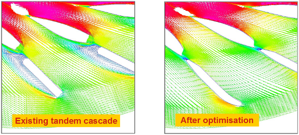
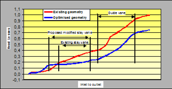
On old machines, the stay vane profile is often very crude and was chosen more to be easy to manufacture rather than to be hydraulically optimised. In such a case, it is generally interesting to modify the stay vanes shape in order to reduce their intrinsic losses as well as to better suit with the guide vanes. CFD calculations allow to judge the stay vanes behaviour improvement (See Fig1) as well as to estimate the losses reduction due to that modification (See Fig2).
The stay vanes being important components of the turbine mechanical structure, special attention must be paid on their modification including checking of mechanical stresses with regard to the existing material, quality of the existing material as well as cutting and welding sequences and procedures.
4. Guide vanes replacement
The high velocity flow along the guide vanes generates a high level of losses The replacement of the existing guide vanes by new more adapted ones generally leads to a significant improvement of the performances. The prototype induced cost is therefore often justified.
4.1. Example of Chute-des-passes project
This power plant, owned by Alcan Inc., is located on Peribonka river, 160 km Northeast of the Lac St-Jean, Quebec, Canada. Chute-des-passes hydraulic power plant began commercial operation in 1960 and four of the five turbines were rehabilitated from 1998 and 2001. The turbines operate at 200 r.p.m. and each of them, equipped with a 3556 mm outlet runner diameter can produce a maximum output of 173 MW at a rated net head of 174 m.
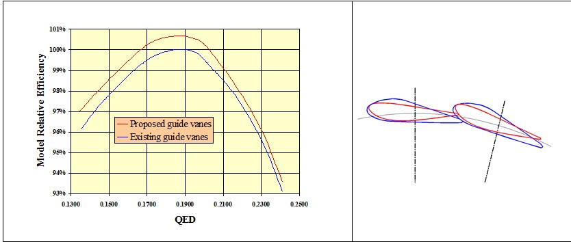
During development, CFD calculations shown that there was an interesting potential in replacing the original profile with an Alstom modern profile. It was therefore decided to compare the two profiles through a model test. The result that was obtained is shown on figure 3. The model efficiency increase was about 0.5% to 0.8% at nED=0.287, which is typical of what happen at other nED. Taking into account performances at three different heads, the model weighted average efficiency increase was around 0.6% leading to around 0.4% after transposition to prototype with the IEC step-up. In addition, this significant efficiency increase based on two sets of model guide vanes with good surface finish is conservative when compared to the prototype where the old guide vanes were much rougher than new guide vanes. For more detailed information, refer to Ref 1.
4.2. Example of Chute-à-la-savane project
This power plant, owned by Alcan Inc., is located on Peribonka river, 15 km upstream of the Lac St-Jean, Quebec, Canada. Chute à la savane power plant began commercial operation in 1953. It is composed of five units operating at 105.9 r.p.m. Each of them, equipped with a 4521 mm outlet runner diameter can produce a maximum output of 51.6 MW at a rated net head of 33.8 m.
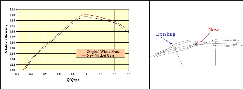
The flow analysis showed a better behaviour with the new guide vanes and thus, in line with the calculation results, it was decided to replace the guide vanes. The new guide vanes present a non-symmetric shape with lower thickness and length compared to the existing shape (maximum thickness and length respectively decreased by about 39% and 8%). The lower length contributes also to reduce the hang over of guide vanes which is favourable for performances and cavitation. The expected gain with the new guide vanes evaluated by numerical investigation was confirmed during model test where the increasing of efficiency was more than 0.7% over the whole operating range (see Fig. 4). For more detailed information, refer to Ref 2.
5. Runner improvement
Even if all the hydraulic components are important and can, by a poor design, badly affect the whole turbine performance, the runner remains the key component to fulfill the guaranteed performances.
Hereafter are some examples requiring a specific runner design.
5.1. Example of Outardes-3 project
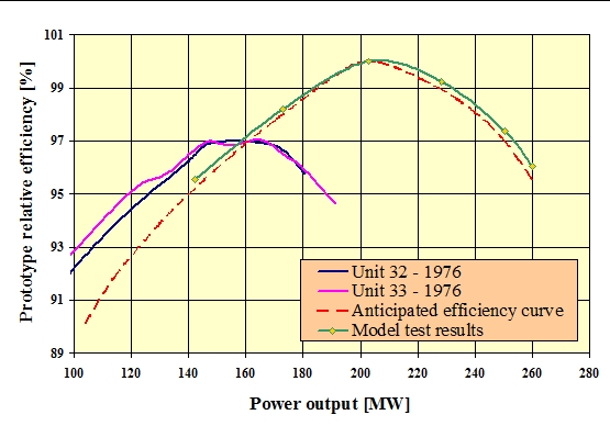
This power plant, owned by Hydro-Québec, is located on Outardes river, 100 km Northwest of the Baie-Comeau, Quebec, Canada. Outardes-3 hydraulic power plant began commercial operation in 1969 and the rehabilitation of the four turbines will be completed in 2006. The new turbines operate at 180 r.p.m. and each of them, equipped with a 4360 mm outlet runner diameter can produce a maximum output of 260 MW at a rated net head of 143.5 m.
The challenge of the new design of the turbines was to deliver an output of 260 MW instead of 193 MW for the original design using a rotational speed of 180 r.p.m. instead of 163.6 r.p.m. for the original units. In addition, the turbine being equipped with a ring gate, this output increase had to be insured with a limited maximum opening angle of the guide vanes to avoid any interference between guide vanes and ring gate.
With regard to the project difficulty, Alstom decided to design and test 2 completely different runners at the early stages of the design process. The selected runner has an exceptionally good behaviour regarding efficiency, output and cavitation characteristics. Figure 5 below presents the prototype performances anticipated from the design tools used by Alstom at the proposal stage as well as the results of the model test. Prototype test results of the original units are also shown. This figure clearly demonstrates that the guarantees formulated by Alstom were perfectly confirmed on the model. The average weighted efficiency obtained on the model is 94.36% in comparison with a guaranteed value of 94.19%. The new peak efficiency is more than 2.5% higher than measured on the original units with an increase in maximum power output of more than 30 %. For more detailed information, refer to Ref 3.
5.2. Example of Shasta project
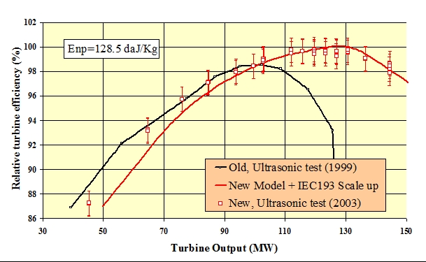
This power plant, owned by the US Bureau of Reclamation (USBR), is located on the Sacramento river, near Redding, California, USA. Shasta hydraulic power plant began commercial operation in 1944 and the described rehabilitation concerns units 3 to 5. The new turbines operate at 138.5 r.p.m. and each of them, equipped with a 3988 mm outlet runner diameter can produce a maximum output of 144 MW at a rated net head of 129.5 m.
The challenge of the new design of the turbines is to deliver an output of 144 MW under 129.5 m instead of 133 MW under 145 m for the original design. The maximum power factor PED has therefore to be increased by 28 %. Moreover, the specific hydraulic energy range of operation is among the largest ever experienced for Francis turbines Emax / Emin = 2.02 and the existing runner inlet diameter is very small in regard to the required new specific speed.
An initial design using a traditional blade thickness was done and CFD viscous calculation indicates that around nominal specific hydraulic energy the efficiency was good even if the blade turning angle was more than 100°.
However as can be seen in Fig 6 (left), the flow pattern was quite perturbed under low head. The design was therefore modified and we obtained a runner blade shape rather similar to the one shown in Fig.6 (right), with a surprisingly high blade thickness at the leading edge but with a much more favourable low head flow pattern. For this design, the hydraulic engineer used, in addition to his experience, the Alstom’s genetic optimiser tool. For more detailed information, refer to Ref 4.
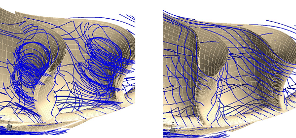
After additional viscous flow calculations to investigate all the main hydraulic characteristics, such as cavitation or losses, both runners presented in Fig.6 were manufactured and tested at Alstom’s technology centre laboratory in Grenoble (France) during the development tests. Model test measurements confirmed the viscous calculations results and the anticipated better behaviour of the thicker runner observed in Fig.6 mainly under the low specific hydraulic energy operating range
Model tests were confirmed by site tests carried out in September 2003. Fig. 7 shows the scaled model test results as well as the site test results. At low load the prototype appears to behave better than expected from the model test, while elsewhere the scale up model results fall well within the uncertainty band of the prototype measurements.
6. Draft tube improvement
With the runner, the draft tube is a major component acting in the turbine behavior. Lower is the head more important is the draft tube performance. Even if the behavior of the existing draft tube is often difficult to predict through CFD calculation, the section law as well as the velocity field at the elbow inlet are very important parameters to consider in order to avoid flow separation and operation instabilities.
Special attention must be paid to the draft tube in case of unit rehabilitation with a flow increase since such an increase can bring a problem that was not existing before rehabilitation.
Example of Chute-a-la-savane project :
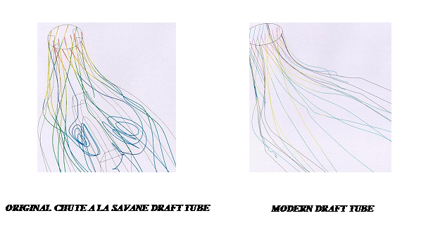
This power plant, owned by Alcan Inc., is located on Peribonka river, 15 km upstream of the Lac St-Jean, Quebec, Canada. Chute à la savane power plant began commercial operation in 1953. It is composed of five units operating at 105.9 r.p.m. Each of them, equipped with a 4521 mm outlet runner diameter can produce a maximum output of 51.6 MW at a rated net head of 33.8 m.
For this project, the output was increased by 15 % and, as a consequence the discharge was significantly increased as well. The existing draft tube was not designed for such a discharge and in such a way the section law was worrying. When compared to a modern design it showed a strong difference, especially in the elbow part, leading to expect a noticeable difference in the flow behavior. That was confirmed by flow calculations (see Fig 8).
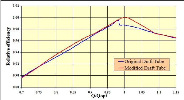
Different solutions were therefore developed and finally after CFD optimization, a modification of the draft tube was proposed. This modification consists basically to decrease the elbow outlet height by covering the lower part of the draft tube to minimize the cost impact.
The poor behavior of the original draft tube was confirmed during model test in which we observed at the optimal discharge severe back flows and instabilities on the upper part of the outlet elbow. At this point a drop of efficiency was measured and correlated with an unbalanced static pressure between the two channels at the outlet of draft tube. The tests performed with the modified draft tube have shown a strong improvement: No drop of efficiency was observed for the optimal discharge without back flow and a better efficiency on the overall operating range was noted (see Fig.9). For more detailed information, refer to Ref 2. In spite of that model results, the draft tube modification was not done on prototype.
7. Conclusion
For new projects the competitors are free to optimise all the necessary parameters in order to propose the best possible guarantees. They therefore rest on the strong basis of their existing designs to improve the necessary parameters involved in the specific project to suit as much as possible to the requirements of the tender specification.
For rehabilitation projects, the specific difficulty is to take into account the existing components and design the new components with full consideration to the existing ones. This difficulty appears at two different stages :
- At the time of the offer. A complete calculation investigation is not often possible at this stage due to the limited study time. In addition, the available documentation on existing components is sometimes quite poor at this initial stage. Simplified evaluation tools have therefore to be used. Those tools used by experimented proposal Engineers are generally accurate enough to determine the correct guarantee levels.
- At the time of execution of the contract. Before to design the new components the behaviour of existing ones must be carefully studied through CFD calculations. It allows the design of new components fully adapted to existing ones. For large units or difficult projects a model test is generally carried out to confirm the performances.
Thanks to deep studies using the most advanced tools and model tests, it is possible to carry out rehabilitation works leading to performance improvements that could have appeared as too ambitious at the first glance in the initial stage of the feasibility study. From the examples described above, it can be seen that ambitious targets can be reached. When speaking of performance improvements one can have in mind the runner only, but it has also been shown that significant improvements can come from other components.
References
- Rehabilitation of the Hydraulic Passageways at Chute des Passes, By Benoit Papillon,Sylvain Giroux, Jean-Louis Gagne and Michel Sabourin – IAHR Symposium September 2002 in Lausanne
- Refurbishment of Low Head Francis Turbines, By Patrick Eberle, Michel Couston and Michel Sabourin.- Hydro Power & Dam 2003.
- Rehabilitation and major upgrade of the Outardes-3 turbines, By Jean-François Caron, Danièle Bazin, Charles Pepin, and Michel Sabourin – Hydrovision 2004 in Montreal.
- Shasta Powerplant refurbishment, By Michel Couston, Benoit Papillon and Danièle Bazin – IAHR Symposium July 2004 in Stockholm
L’Encyclopédie de l’Énergie est publiée par l’Association des Encyclopédies de l’Environnement et de l’Énergie (www.a3e.fr), contractuellement liée à l’université Grenoble Alpes et à Grenoble INP, et parrainée par l’Académie des sciences.
Pour citer cet article, merci de mentionner le nom de l’auteur, le titre de l’article et son URL sur le site de l’Encyclopédie de l’Énergie.
Les articles de l’Encyclopédie de l’Énergie sont mis à disposition selon les termes de la licence Creative Commons Attribution – Pas d’Utilisation Commerciale – Pas de Modification 4.0 International.